
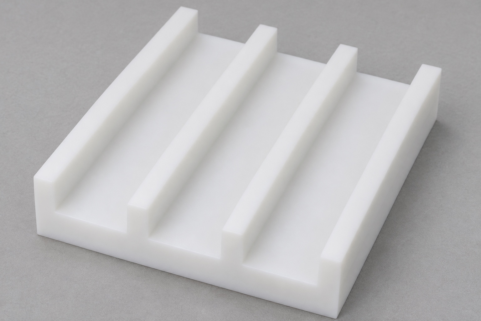
Define three open channels and a continuous base
A divider block for inert electrophoresis accessory staging should be specified as a manufactured geometry, not as a proven assay accessory. This example is a white POM-C rectangular block with three parallel open-top channels extending from one end to the other. Four raised lands border and separate the channels, whose flat floors leave a continuous solid base below. There are no through-slots, holes, threads or inserted parts. The guide covers drawing-based CNC milling and inspection, not electrical operation, sample protection, chemical compatibility or electrophoresis performance in working laboratory equipment.

State what each channel and land is intended to do
Identify the inert reference envelope and whether a floor supports it, a wall locates it or a land merely separates adjacent positions. Similar-looking channels do not prove equal functional requirements. The designer should specify clearance, contact and insertion direction before assigning tolerances. A reference that can be placed in a channel does not establish its location relative to neighboring channels. Define the relationship to external datums and any surfaces that must remain clear. This makes the inspection plan evaluate the intended interface rather than a convenient overall width or visually regular pattern.
Separate channel width from spacing and land thickness
Three channel widths, the locations of those channels and the four remaining lands are distinct features. Overall block width alone cannot prove them all. Choose an unambiguous dimensioning scheme tied to stable references, avoiding an accidental chain that hides where variation may accumulate. State whether equal spacing is required and which relationships are functional. A single gauge that enters one channel does not establish the whole pattern. Inspection should cover the required locations and sections along the length, not just the easiest opening where access is generous and burrs are most visible.
Distinguish floor depth from remaining base material
Channel depth measured from a land top is not automatically the same question as material remaining beneath the floor. The answer depends on overall height, top and underside geometry and their relationships. Define any minimum base requirement directly and agree its measurement coverage. The channels in this example open at both ends but not through the underside. Do not extend them through the base for convenient chip removal without approval. Also define floor-to-wall transitions, because a tool-generated radius can reduce the usable contact area even when nominal channel width and depth appear correct.

Specify the exact POM-C grade and outgoing condition
POM-C identifies acetal copolymer, not a complete specification for every grade or exposure. Define the required formulation, color, stock form and supporting documentation. White appearance does not establish chemical compatibility, cleanliness or suitability for laboratory electrical equipment. Do not substitute another acetal family or a filled grade without approval. Material association should remain with the blank through milling, cleaning and packaging. If marking a channel is unacceptable, preserve identification outside functional surfaces. The guide reports no sterilization, chemical or sample test; those requirements need separate review for the actual material, part and use conditions.
Support the base instead of squeezing the raised lands
Review jaw contact, lower support and tool access as material is removed. The continuous base offers a different workholding opportunity from the raised lands between channels. Gripping slender lands may restrain or deform the features whose released geometry matters. Protective jaws must match the actual component, not simply reproduce a familiar metal-part setup. State whether final acceptance applies to the released part or a defined restrained condition. A reading obtained while the block is compressed in a vise should not silently represent its supplied state. Preserve the reference faces needed to reconstruct the inspection alignment afterward.
Coordinate channel roughing and finishing with changing support
Removing the three channels changes the section supporting subsequent cuts. Plan roughing, floor finishing, wall finishing and end access so that later work does not damage or obscure an earlier feature. Choose tool geometry, chip evacuation and heat management for the actual grade, machine and setup. Do not infer a universal feed, coolant or waiting time from the polymer name. Any intermediate treatment or stabilization condition should be approved and recorded. The process record should permit later interpretation of measurements rather than claiming that an arbitrary delay proves long-term stability under all storage or service conditions.
Control both channel exits and longitudinal edges
Each open channel has two ends and long wall-to-land edges. Plan access to all of them after milling. Deburring should not widen the channels, thin lands or round away the defined floor contact region. Specify permitted edge breaks instead of relying on an attractive overall finish. The underside and base edges also deserve review for handling and support. Reinspect relevant features after final finishing. If removing a burr requires a new relief or a geometry change, obtain approval first; workshop convenience is not authority to turn an open channel into a through-slot or change the pattern.
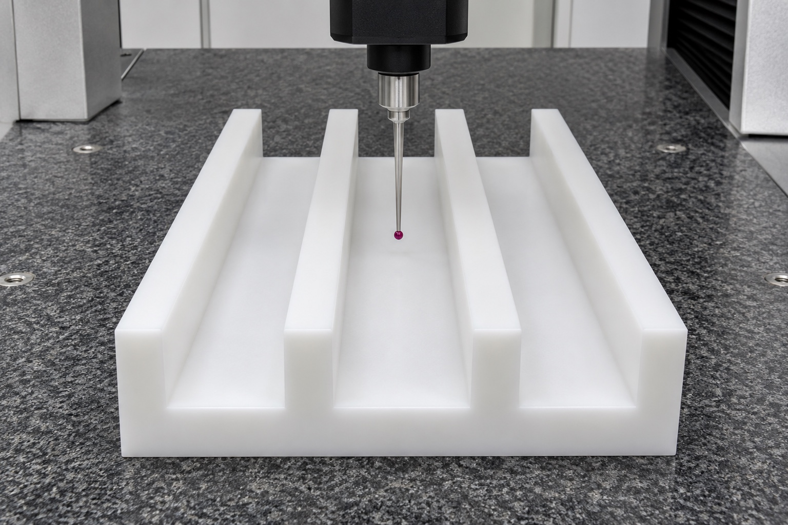
Inspect the full pattern in the agreed final state
The first-article plan should cover exterior references, overall dimensions, channel widths and locations, floor depths, lands, base material and required relationships. Choose alignment, support and contact force appropriate to the polymer. A coordinate probe may evaluate some features, while optical or other methods may address access and edge definition. No instrument name proves complete coverage. A top image does not establish all floor depths or the underside. Record actual results and method limitations when real components are inspected. CAD nominal values define the target and must not be reported as readings from a manufactured block.
Keep inert staging observations separate from laboratory validation
Known inert reference pieces may help observe placement, contact and separation within the channels. Identify reference revisions and conditions, and interpret each observation alongside the component's dimensional record. Easy insertion alone does not establish location, retention or correct separation of actual accessories. It also does not prove sample integrity, assay reproducibility, electrical isolation, contamination control or safe operation in electrophoresis equipment. Those questions require their own design assessment and appropriate tests. This manufacturing guide describes a limited staging geometry and does not convert an unpowered fit observation into a validated laboratory workflow or measured performance claim.
Define channel cleaning and protective packaging explicitly
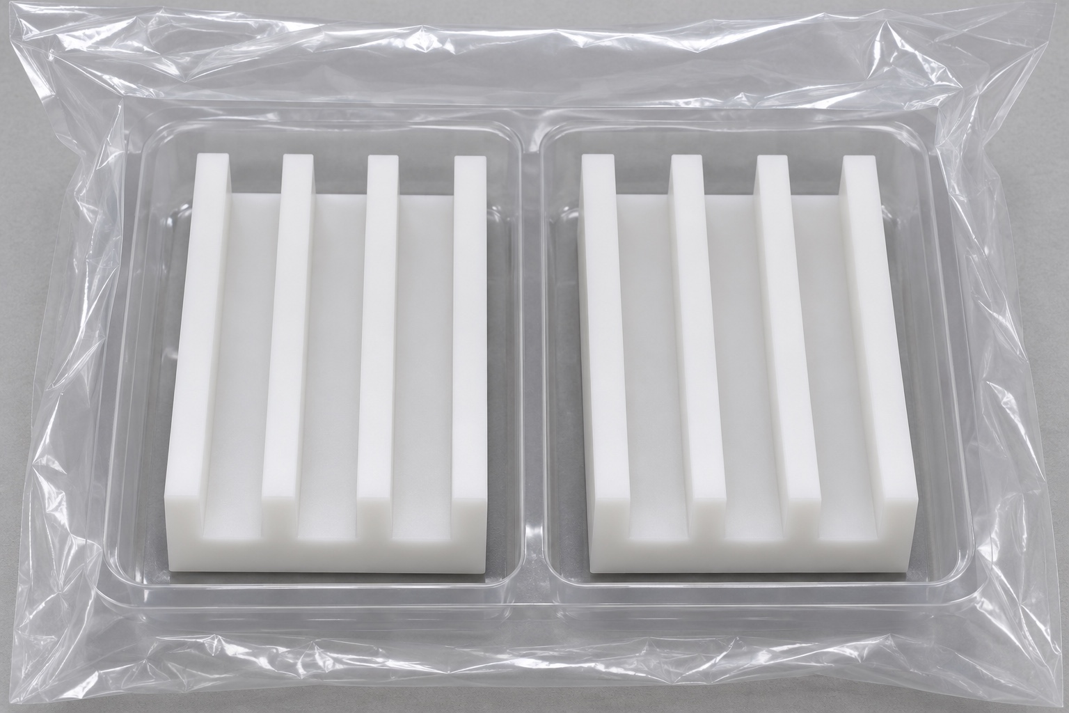
Open ends provide access but do not prove that chips or residues have been removed from floor transitions and wall edges. Specify the outgoing cleaning requirement and any needed verification. Packaging should support the base, avoid forcing the lands into a distorted position and prevent adjacent blocks from nesting together. Keep identification outside functional contact regions. A clean-looking tray is not a sterile barrier, particle result or validated shipping arrangement. If the application requires contamination limits or special storage, agree the material compatibility, methods and responsibilities before production instead of relying on the appearance of white plastic.
Build an RFQ around the complete three-channel pattern
Supply the drawing, model, quantity, exact POM-C grade, final state, datum system, channel definitions and land or base requirements. Identify inspection locations along the channel length and any minimum remaining material. Ask for DFM comments on tool access, changing support, end-edge control and released measurement. Separate prototype quantities from later small batches without assuming identical process effort. Define any inert reference observation and complete-equipment qualification independently. A precise inquiry supports custom precision plastic medical and laboratory fixture parts without inventing assay results, generic manufacturing capability or compatibility absent from the approved technical scope.
FAQ
Are the three channels cut through the underside?
No. They open at the top and both ends but retain flat floors above a continuous solid base. A through-slot would be a different geometry and must not be introduced without design approval.
Does overall width establish the complete channel pattern?
No. Channel widths, locations, land thicknesses and their relationships are separate requirements. Use a clear datum-based dimensioning and inspection scheme rather than relying on one exterior dimension or a visual pattern.
Is channel depth sufficient to establish remaining base thickness?
No. Overall height and surface relationships also matter. Define any minimum base requirement and an appropriate evaluation strategy separately from depth measured from a land top at one location.
Why inspect the block after releasing the vise?
If acceptance applies to the supplied released part, inspection should represent that state. Jaw restraint and contact force can influence readings, so support and measurement conditions must be explicitly agreed.
Does white POM-C prove laboratory compatibility?
No. Specify the exact grade and evaluate the real chemical, electrical, cleaning and use requirements separately. Color or polymer family alone does not establish sample protection, compatibility or validated equipment performance.
Can an inert staging check replace equipment validation?
No. It supports only its defined placement, contact or separation observation with known references. Assay performance, electrical safety, contamination control and actual equipment qualification need separate appropriate assessment and evidence.

tanghangyun@oemach.com