
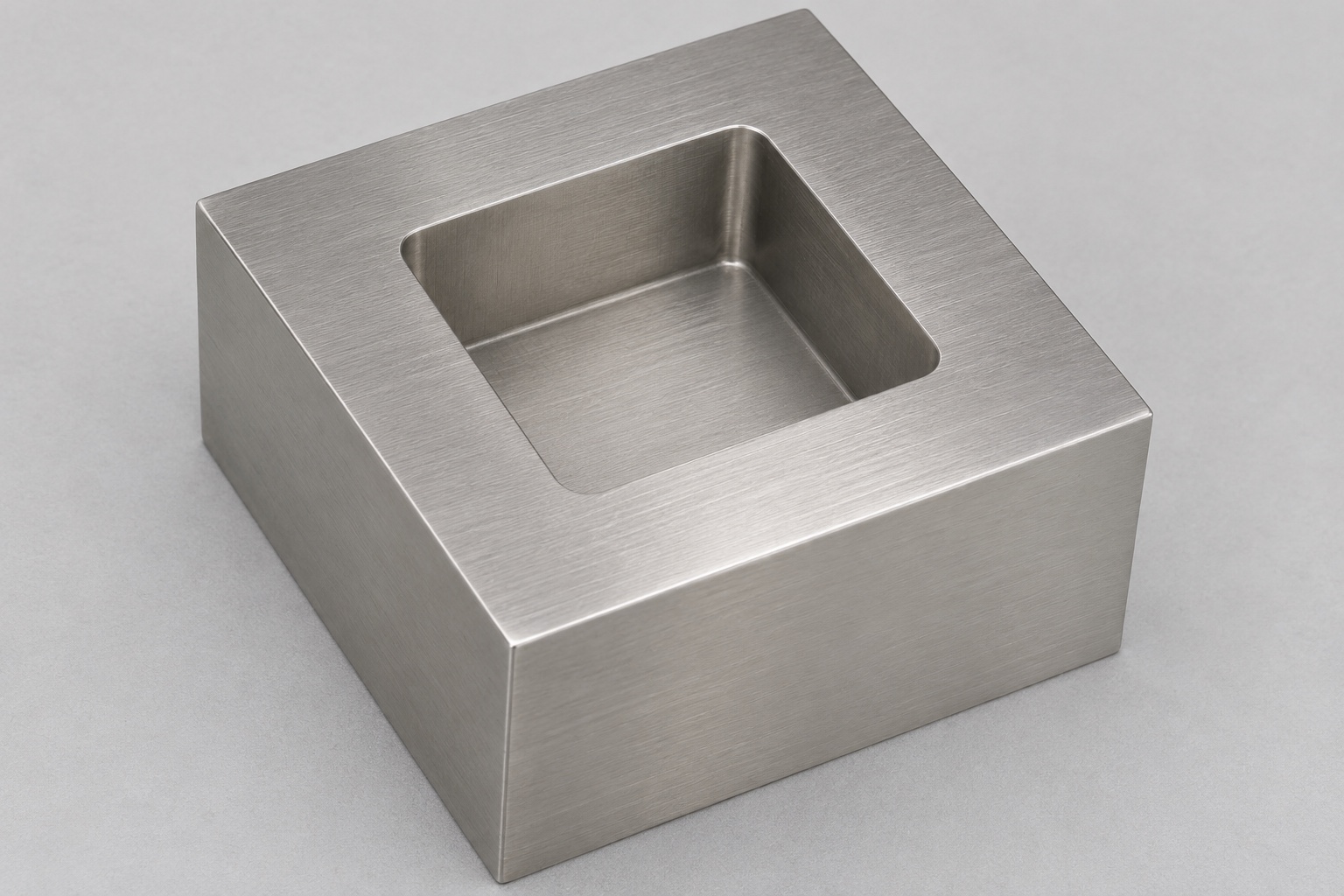
Start with a blind pocket rather than an assumed socket standard
A square-pocket indexing block for an inert endoscope service fixture needs more definition than a square width on a model. This example is a plain 316L stainless steel cuboid containing one centered blind square pocket. The pocket has four walls, rounded internal vertical corners and a flat floor above a closed bottom. There are no mounting holes, threads or auxiliary slots. The guide explains drawing-based CNC milling and inspection; it does not establish torque capacity, compatibility with a particular endoscope or a validated medical maintenance procedure.

Identify the surfaces that actually control the reference
Decide whether the inert mating reference is intended to contact opposing walls, rest on the pocket floor or remain clear of one of those surfaces. These alternatives lead to different functional requirements. Identify a stable external datum system and the pocket's required relationship to it. A centered appearance does not prove location or angular orientation. If the floor is only clearance, do not silently use it as the seating datum during inspection. Record the intended contact and clearance regions so that a manufacturer can distinguish a meaningful tolerance from a general cosmetic expectation.
Give internal corner clearance its own drawing definition
A rotating end mill leaves an internal corner radius; a nominally square male reference may therefore interfere at its corners even when opposite-wall spacing is correct. Define the pocket radius and the mating reference envelope together. Specify any intended relief rather than adding an unapproved corner hole or slot in the workshop. Smaller cutters and different processes involve their own access and stability questions. A model with sharp corners is not evidence that ordinary milling can reproduce them. The DFM discussion should resolve the actual geometry before a quote is treated as a production commitment.
Separate pocket depth from remaining floor thickness
Pocket depth is measured from a defined reference surface to the floor. Remaining material beneath that floor depends on the outside geometry and its relationship to the pocket. A conforming depth reading alone does not establish a minimum bottom thickness across the whole floor. Define thickness requirements and measurement coverage explicitly if they are functional. The floor must remain closed in this example. Also state permitted floor-to-wall transitions: the tool's convenient tip shape should not silently become the accepted bottom geometry when a mating reference or inspection method requires something different.
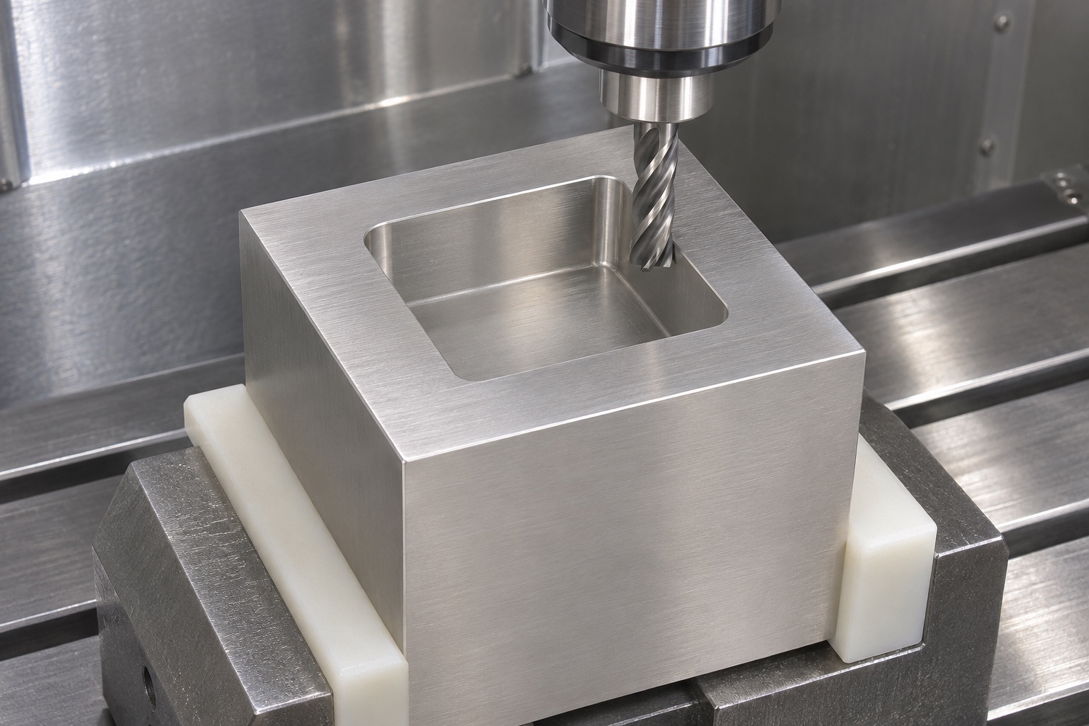
Keep 316L identity and surface condition explicit
Specify the required 316L material definition, stock form and documentation. Maintain material association through blank preparation, milling, secondary work and outgoing cleaning, including when direct marking of a functional face is restricted. A bright machined finish does not prove a particular alloy, passivation process or cleanliness level. Any treatment needs its own scope and acceptance condition. The alloy designation does not independently qualify the finished block for cleaning chemicals or sterilization exposure. Those questions depend on the exact component, finish and use conditions and should remain separate from the proposed machining route.
Support the block while preserving useful inspection references
Review support beneath the block, jaw contact on the exterior and clearance above the pocket. The fixture must resist cutting loads without concealing or damaging the references needed later. Plan how external datum faces are established and recovered if the block is transferred to another setup. A protective jaw is a workholding choice, not proof of attained position or flatness. Avoid using an unfinished surface as a final datum merely because it is convenient to grip. The sequence should leave a clear connection between the approved drawing and the alignment used for acceptance.
Plan cavity entry and finishing with realistic tool access
Review tool diameter, projection, holder clearance and the route for entering a closed cavity. The fact that a tool fits inside the opening does not establish a stable finishing path at full depth. Coordinate roughing, wall finishing, corner work and floor finishing so that later operations do not damage previously completed features. Select parameters for the actual 316L, machine and tool rather than copying a universal recipe. If the requested depth or corner radius needs another approach, document the limitation and obtain approval before production. No cycle time or achieved tolerance is claimed here.
Deburr the opening without enlarging the functional pocket
The opening edge needs a defined condition, particularly where an inert reference enters or is removed. Remove unintended burrs without increasing opposite-wall spacing, excessively rounding the rim or changing the usable pocket depth. The bottom corners and transitions also need review for residual chips and unapproved geometry. A general polishing step is not a substitute for controlled edge requirements. Inspect relevant features after final edge work, not only before it. If reaching an edge would require a new relief, return the issue for design review instead of altering the square-pocket interface without authorization.
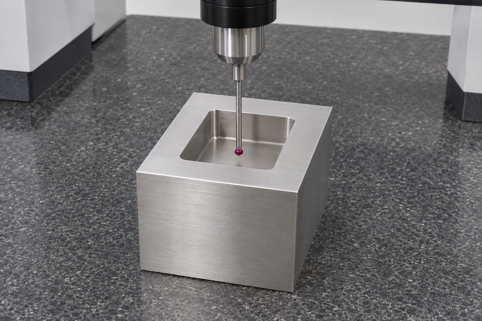
Match inspection coverage to walls, corners and floor
A first-article plan should cover outside datums, pocket location, opposite-wall spacing, wall orientation, corner radii, depth, floor condition and any remaining-thickness requirement. Choose methods with suitable access and alignment. A depth probe does not establish wall form or all corner clearances; an overhead image does not establish the full wall height or underside. A CMM can be useful only where its probe and strategy evaluate the specified features. Record the actual methods, conditions and results on real parts. Neither nominal CAD dimensions nor an instrument photograph is a dimensional acceptance report.
Treat an inert insertion check as supplementary evidence
A controlled square reference may help observe entry, contact location and whether the intended depth is accessible. Identify its revision and corner geometry, not just its width. A loose fit can reflect excess clearance, while an obstruction can come from either component, so a hand check cannot replace drawing inspection. It does not establish torque transmission, wear, repeated service performance or compatibility with working medical equipment. The responsible designer must define separate qualification where those functions matter. Report only the limited observation performed and keep it distinct from acceptance of measured features.
Define cleaning and protective handling for a blind cavity
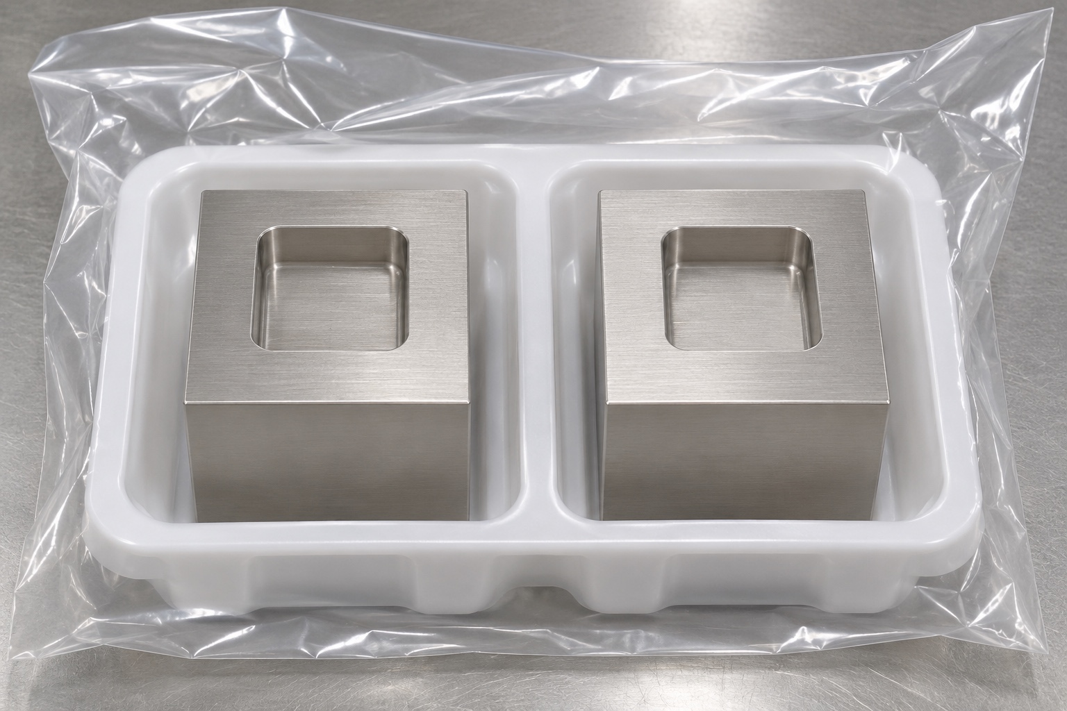
A closed floor means machining debris cannot simply pass through the part. Plan access to the floor, internal corners and opening for the agreed outgoing cleaning and verification. Specify residue limits if required rather than relying on a clean-looking photograph. Packaging should isolate the block and keep protective material from becoming trapped in the cavity or abrading functional walls. Preserve revision and material identification outside sensitive surfaces. A protective tray and bag are not a sterile barrier or a validated transport system. Any additional cleanliness or shipping requirement needs explicit methods and evidence.
Request a quotation that connects each requirement to a check
Provide the revision-controlled drawing, model, quantity, material definition, datums, pocket dimensions, corner geometry, depth and final condition. Highlight floor thickness, contact boundaries and required inspection coverage. Ask for DFM comments on cavity entry, cutter reach, reference recovery and probe access. Separate prototype and small-batch needs without assuming identical effort. Define the inert mating reference and any additional system tests as distinct tasks. A precise RFQ lets a supplier evaluate custom medical fixture machining without inventing a standard socket fit, a proven customer result or a performance claim absent from the drawing.
FAQ
Can a milled square pocket have perfectly sharp internal vertical corners?
Not from an ordinary round end mill alone. Define a manufacturable radius or an approved alternative process and check the mating reference's corners. Do not add relief holes without design approval.
Does pocket depth prove the remaining bottom thickness?
No. Bottom thickness also depends on external dimensions, floor geometry and their relationships. Specify the minimum material and the method and coverage needed to evaluate it separately from a single depth reading.
Can a square reference replace dimensional inspection?
No. It can support a defined insertion or contact observation, but its own width, corners and condition must be known. Drawing acceptance still requires methods covering the specified component features.
Is the pocket floor always the functional seat?
No. The design must state whether the floor locates, contacts or provides clearance. Wall contact and depth requirements should follow that definition, not an assumption made during machining or inspection.
Does 316L mean the finished block is sterilization qualified?
No. Exact material, finish, exposure and equipment requirements need separate review. The material designation alone does not establish cleaning efficacy, sterilization compatibility or approval for a medical maintenance process.
What should a first-article inspection record include?
Include revision, material, final state, datum alignment, methods and real results for walls, corners, depth, floor and other specified features. Declare measurement limitations rather than copying nominal CAD values into result fields.

tanghangyun@oemach.com