
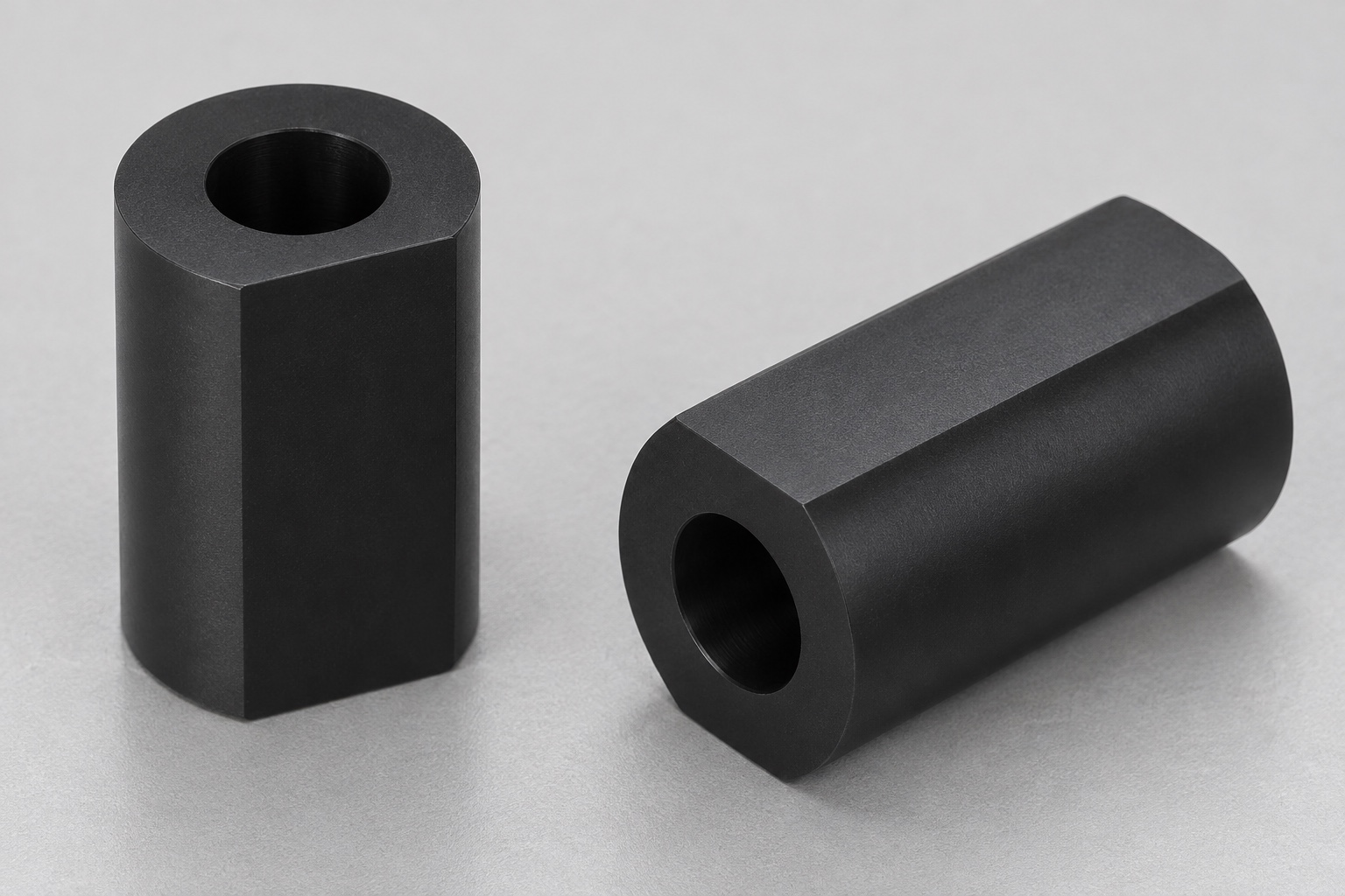
Distinguish the circular bore from the external D-profile
A D-profile bushing can have a circular internal bore while its outside includes one longitudinal flat. Those features serve different interface questions and should not be combined into an ambiguous D-shaped hole callout. This guide discusses a short black POM-C bushing for an inert diagnostic cartridge fixture study. It has one centered circular axial through-bore and one full-length external flat, with no flange, slot, groove, thread, insert or bearing. Precision CNC machining begins with that clear geometry, not with an assumed torque capacity or a claimed fit in a working diagnostic instrument.

Define which surfaces locate and which remain clear
The bore may locate a reference shaft while the exterior engages a mating pocket, but the designer must state the intended arrangement. Identify whether the flat provides orientation, contact or clearance and whether the round outside also locates the part. A convenient assembly observation cannot establish those roles afterward. Specify the relevant datums and the relationship between the bore axis and external flat. Avoid giving the exterior a tight general tolerance without deciding what actually controls the interface. The whole mating arrangement needs review before dimensions become meaningful acceptance requirements.
Dimension the flat relative to the bore axis
The distance from the bore axis to the external flat can matter independently of outside diameter and bore size. Define that relationship directly or through an unambiguous approved datum system. The width of the visible flat is not always a sufficient substitute because it depends on the remaining round profile as well. State any required longitudinal alignment and permitted edge transition. A circular bore does not automatically establish the correct flat orientation or position. Use a drawing that allows both the machinist and inspector to reconstruct the intended relationship without guessing from the rendered component.
Specify the exact POM-C grade and supplied condition
POM-C identifies acetal copolymer, but a real order still needs the required grade, color, stock form and supporting documentation. Black appearance does not establish a specific formulation, additive package or suitability for an exposure. Do not substitute a different acetal material or filled grade without approval. Define any application-specific compatibility review separately from the machining specification. This guide asserts no biocompatibility, sterilization resistance, chemical test or clinical suitability. Material identity and traceability are necessary inputs to the manufacturing record, not a shortcut to approving the finished bushing for an operating medical system.
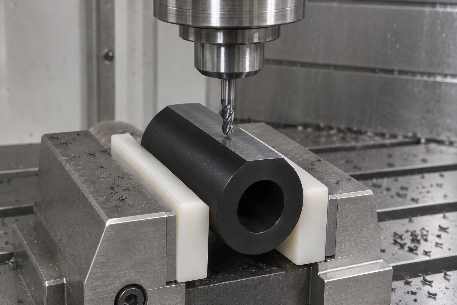
Coordinate CNC turning and milling in the process plan
Turning can establish accessible round features and the circular bore, while a milling operation can create the single external flat. The sequence should preserve sufficient support and recover the required references when transferring between setups. Review how the bore, outside and end faces are established and which features are used to locate the flat. Neither a turned round blank nor a convenient vise face automatically supplies the final datum relationship. The proposed route must fit the actual dimensions, material and tolerance requirements. No universal cutting parameters or achieved machining accuracy are claimed here.
Review clamping as the section becomes asymmetric
Removing the flat changes the section from a full cylinder to an asymmetric profile. Consider how the jaws contact the part before and after that operation. Excessive restraint can change the measured bore or outside shape, while inadequate support can permit movement during cutting. Protective jaws should match the workholding task without adding an unapproved feature to the bushing. Identify the condition used for final acceptance: an inspection performed while the component is squeezed in a fixture may not represent its released state. The drawing and inspection plan should make that distinction explicit.
Control chips and heat with a material-specific route
Machining a polymer is not the same process as cutting a visually similar metal cylinder. Tool geometry, chip evacuation, heat management and support should be selected for the specified POM-C grade and actual setup. Do not invent a universal coolant, waiting period or feed from the material name alone. If an intermediate treatment or stabilization condition is proposed, obtain approval and record it. The transition from machining to inspection should preserve enough process information to interpret results. An arbitrarily chosen delay does not prove long-term dimensional stability under later storage or service conditions.
Deburr the bore mouths and the single external flat
The circular through-bore has two mouths, and the flat creates two longitudinal transitions into the remaining round outside. Plan access to all of those edges. Remove unintended burrs without enlarging the bore, rounding the flat excessively or creating additional flats. End-face edge breaks should follow the drawing rather than a generic polishing habit. Reinspect relevant features after final edge work. A neat-looking front end cannot establish the condition of the rear bore mouth or the entire length of the external transition. Explicit edge requirements make deburring a controlled operation rather than an undocumented geometry change.
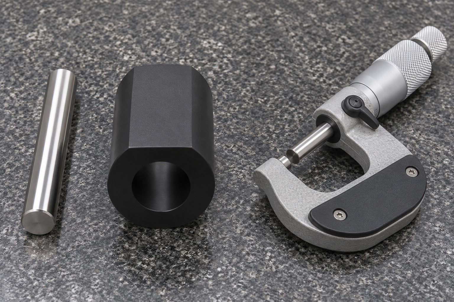
Inspect the released bushing with suitable contact and alignment
The inspection plan should cover bore diameter and form where required, outside profile, length, flat position and the specified relationships. Select alignment, support and contact force appropriate to the polymer and the acceptance question. A pin gauge can address its defined bore limit but does not establish the external D-profile. A micrometer reading across one direction cannot prove every relationship. Coordinate or optical methods may supplement measurements if they can evaluate the required features. Record actual results, conditions and limitations when real parts are inspected; do not treat instrument names as evidence of complete compliance.
Separate anti-rotation geometry from torque performance
The name anti-rotation bushing describes an intended interface feature, not a verified torque rating. A matching inert pocket may allow the team to observe orientation and clearance, but the result depends on both components and the assembly condition. The observation does not establish retention force, wear life, creep, repeated-cycle performance or suitability in an operating analyzer. Those questions require their own defined design assessment and tests. Keep dimensional acceptance separate from supplementary fit checks. This distinction helps a drawing-based supplier provide useful geometry evidence without promising functions that the proposed machining study has not evaluated.
Clean and package without forcing the D-profile
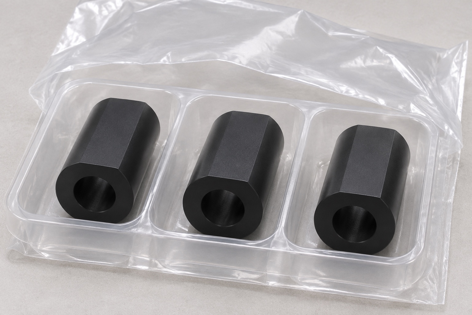
Define the outgoing debris and residue condition, especially for the through-bore and flat transitions. Select cleaning and handling methods compatible with the specified material and any additional requirements. Packaging should separate bushings so that bores and flats are not scratched or forced into a distorted shape. Do not assume that pressing the parts tightly into a tray is harmless. Preserve grade and revision identification outside functional surfaces. Protective packaging is not a sterile barrier or a validated cleanliness result. If particular particle limits or shipping conditions matter, specify the requirements and supporting verification before production.
Prepare a precise inquiry for custom acetal bushings
Provide the drawing, model, quantity, exact POM-C grade, bore specification, exterior profile, flat-to-axis relationship, end geometry and final condition. Identify which dimensions need actual first-article readings and which checks may use an approved gauge. Ask for DFM review of turning-to-milling reference recovery, asymmetric clamping and measurement access. Prototype and small-batch quantities should share controlled requirements without assuming identical production effort. State separately any mating-reference observation or system qualification. A focused RFQ makes precision plastic medical parts easier to evaluate by connecting each requirement to a manufacturing or inspection decision.
FAQ
Is the bore D-shaped in this bushing?
No. The proposed bore is circular and passes axially through the part. A single longitudinal flat on the outside creates the D-shaped external profile. These are separate drawing and inspection features.
Does the external flat establish a torque rating?
No. It defines geometry intended for orientation or anti-rotation contact. Torque capacity, retention, wear and repeated-cycle behavior depend on the complete interface and require separate defined assessment.
Can bore inspection establish the position of the flat?
Not by itself. The inspection must also evaluate the specified relationship between the bore axis and flat, using appropriate alignment and methods. A bore gauge alone does not cover the external profile.
Is black POM-C interchangeable with any acetal stock?
No. Specify the required grade, color, stock form and documentation. Differences in formulation or material family should not be accepted as automatic substitutes simply because the finished parts look similar.
Why review measurements after releasing the clamp?
If the part is supplied and accepted in a released state, its inspection should represent that condition. Clamping and contact force can influence readings, so support and measurement conditions must be agreed.
What should a small-batch bushing RFQ include?
Include the revision-controlled drawing, exact material grade, quantity, bore and outside dimensions, flat-to-axis relationship, edge requirements, final condition and inspection scope. Define supplementary fit observations separately from acceptance.

tanghangyun@oemach.com