
Define the pin before selecting a turning cycle
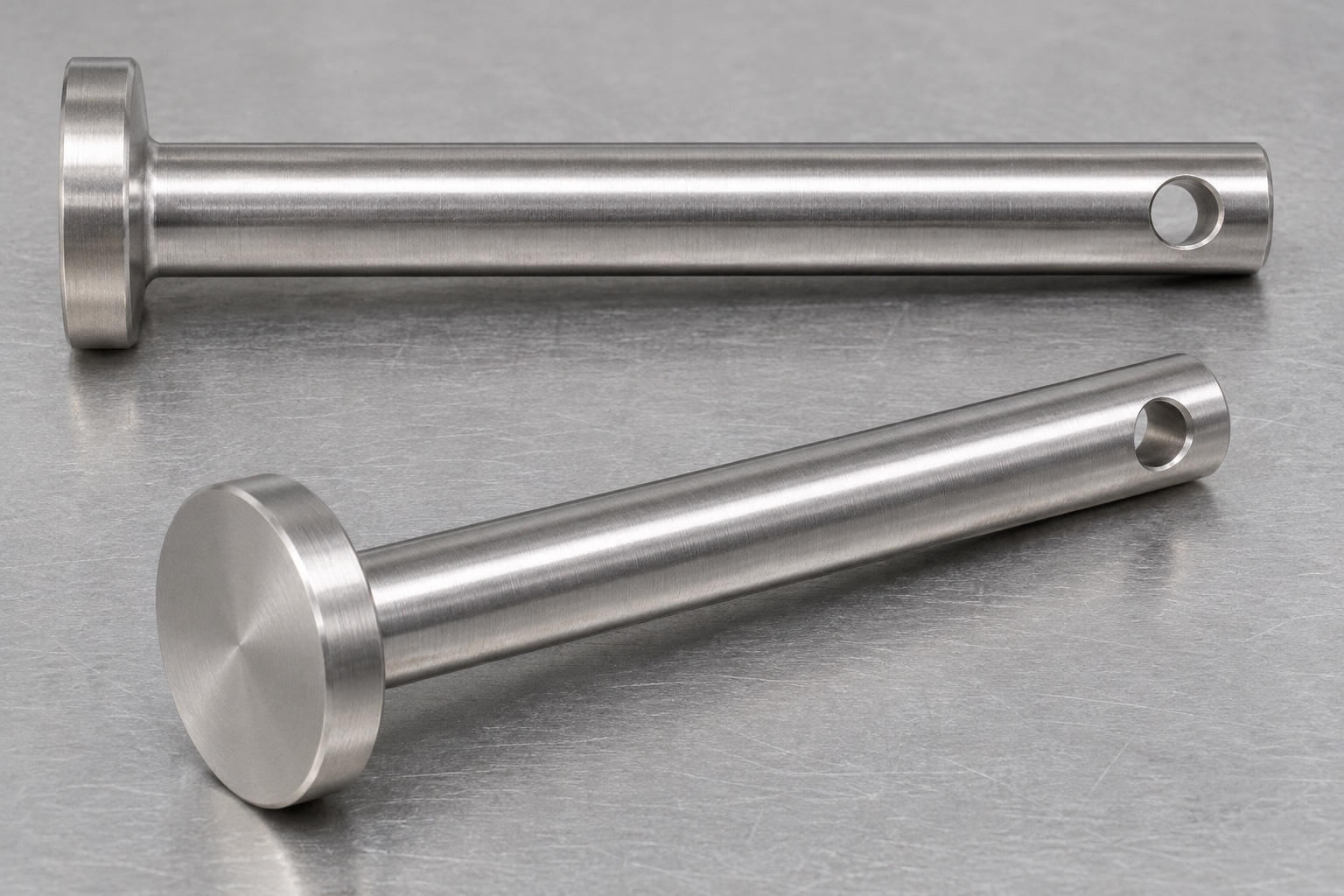
A headed pin for an inert medical cart locking fixture has several interfaces that should not be combined into one generic diameter requirement. The representative geometry is a straight cylindrical shaft, an integral wider flat circular head and one transverse through-hole near the opposite end. There are no threads, axial bores or retention grooves. The shaft locates or clears the fixture, the head provides a stop, and the cross-hole may accommodate a separately defined retention reference. This guide concerns component manufacture and inspection. It does not establish a cart load rating, a safe locking mechanism or suitability for use around a patient.

Establish a meaningful head-shoulder reference
Decide which face of the head contacts the fixture. For the proposed headed pin, the underside shoulder is the natural candidate for installed projection, but the actual drawing must confirm its role. Distinguish overall length from the distance measured from that shoulder to the free tip. The cross-hole position should use the reference required by the assembly rather than an arbitrary convenient end. If head thickness also matters, specify it independently. Measuring overall length and subtracting a nominal head thickness is not equivalent to directly evaluating the required shoulder-to-hole relationship when the drawing controls that relationship as a separate feature.
Separate shaft size from form and installed freedom
Specify the required shaft diameter, usable length and any form or orientation controls. A pin that passes through one dummy opening has demonstrated only a limited assembly observation, not every drawing requirement. Review the entry edge at the free tip and the shoulder transition beneath the head. A large chamfer may reduce the usable engagement length, while an unapproved radius under the head can prevent complete seating against the fixture. The receiving bore and pin must be reviewed together when defining the interface. Do not solve a difficult fit by polishing the shaft until one reference accepts it without checking the approved size and geometry first.
Keep 316L identity through short-part handling
State the stainless steel designation, stock form, supply condition and required records in the quotation package. A visually similar stainless grade is not an automatic replacement. Associate cut blanks and work-in-process trays with the material identity and drawing revision, especially when several pin types share the same manufacturing area. Specify whether direct marking is permitted on functional surfaces or whether identification must remain on the container. The material record supports traceability but does not independently prove corrosion life, cleaning compatibility or completed-lock performance. Any substitution or additional surface treatment should be reviewed before it changes the approved manufacturing route or outgoing inspection condition.
Turn the shaft and head with recoverable references
Plan facing, shaft turning, head formation and separation from stock around the actual part dimensions, tooling and workholding. Decide how the head shoulder and shaft axis will be recovered for later cross-drilling. Keep roughing allowances and final contact surfaces distinct in the process plan. An operation that looks efficient in isolation can create an inconvenient or ambiguous reference for the next setup. The manufacturing engineer should select and verify cutting conditions for the specific stock and machine rather than rely on a universal recipe for 316L pins. Actual component measurements are needed before an achieved accuracy or repeatability statement is justified.
Prevent rolling during the cross-drilling setup
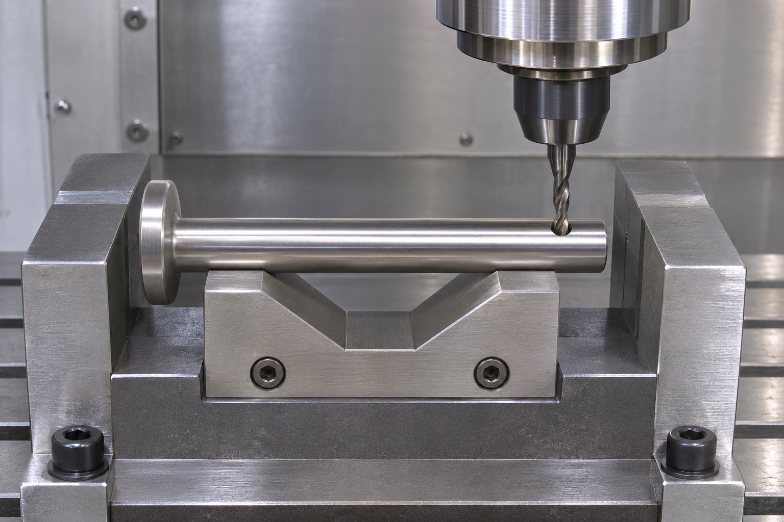
The transverse hole requires a setup that locates the shaft axis, controls the required axial position and prevents the pin from rotating under the drill. Review supporting contacts, clamping locations and clearance beneath the exit. A V-block or dedicated nest may be appropriate, but its geometry and contact condition must suit the actual pin. Avoid clamping against loose chips or damaging the finished shaft. The hole is the only angularly distinct feature on this rotationally symmetric part, so do not invent an orientation datum that the design does not require. If another assembly feature makes angular orientation functional, add that requirement explicitly to the controlled drawing.
Review curved entry and exit as drilling conditions
The drill meets a curved shaft surface at entry and exits another curved surface. Review stability, tool approach and the transition through breakthrough for the actual tool and stock. These are process-planning questions, not permission to add a flat or change the shaft profile without approval. Define any allowable local edge treatment or prepared surface in the drawing before manufacturing. Do not transplant cutting values from an unrelated tool recommendation into an RFQ as a guaranteed recipe. The proposed sequence should keep the exit accessible for inspection and leave a practical method for removing unacceptable attached material without altering the transverse opening beyond its requirements.
Distinguish deburring from enlarging the retention opening
Inspect both cross-hole mouths and the accessible internal passage after loose chips are removed. The curved intersection makes it important to distinguish an attached burr from an intentional edge break. Define permitted chamfer or edge treatment where it affects the separately approved retention reference. Aggressive hand finishing can change the useful hole boundary or reduce surrounding material. A retaining item that can be pushed through does not prove that the hole is correctly sized or free from unacceptable damage. Select a deburring and visual inspection approach with suitable access and magnification where needed, and disclose any area that cannot be evaluated credibly.
Build a feature-by-feature first-article report
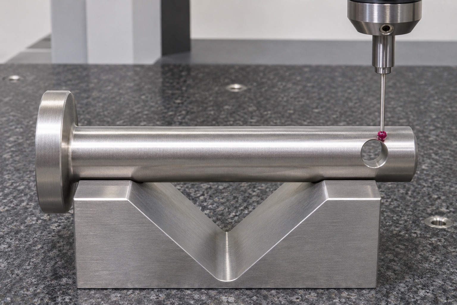
Map shaft size and form, head thickness, shoulder condition, overall length, hole size and hole location to appropriate methods. Identify the part state, supports and reference alignment. A coordinate probe near the cross-hole can illustrate a possible setup, but the photograph contains no measured value. The report must use actual readings from a manufactured pin rather than CAD nominal values. If a method evaluates only part of the hole boundary, state its scope instead of implying complete coverage. A passing diameter check cannot establish the shoulder-to-hole position; each acceptance requirement needs evidence tied to the drawing rather than a generic list of available instruments.
Limit supplementary fit observations to an inert assembly
An approved dummy cart bracket and retention reference can show insertion access, visible seating and interference under a defined condition. Record their revisions and the observation procedure. Do not extrapolate from hand insertion to retention force, vibration resistance, lock life or safe equipment support. Those claims need separately approved system requirements and testing. If the head seats only after force is applied, investigate the measured interfaces before reworking the pin. The component supplier and fixture design owner should agree how an observed discrepancy is reviewed so an informal shop-floor adjustment does not silently become a change to the released locking design.
Preserve the shaft and cross-hole during handover
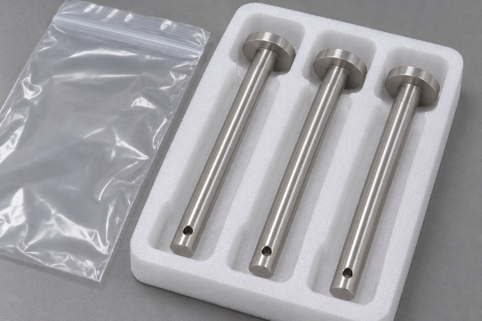
Specify cleaning agents, drying and outgoing handling requirements before shipment. Remove loose debris from the cross-hole and protect the shaft and head shoulder against rubbing during storage. Separate pins where metal-to-metal contact could damage the defined interfaces. Packaging must not leave unacceptable fibers or particles in the small opening. Label packages with part and drawing revision linked to the required material and inspection records. Protective packing is not a sterile barrier, and ordinary cleaning does not establish a numerical residue limit. Receiving inspection should use the actual purchase specification rather than treating a bright finish and sealed bag as complete evidence of conformity.
Request a drawing-based quotation for custom pins
Provide the released drawing and model, 316L requirements, quantity, finish and documentation expectations. Highlight the shoulder reference, shaft interface, transverse-hole definition and permitted edge treatment. Include the dummy-fit observation only if it is requested, with a defined scope separate from dimensional acceptance. Ask the supplier to identify cross-drilling, deburring and measurement limitations during DFM. Preserve approved setups and actual first-article records for repeat low-volume CNC manufacture. A clear RFQ lets suppliers quote the same bounded machining task without inventing load capacity, medical approval, completed customer delivery or a universal precision claim unsupported by the real part and inspection evidence.
FAQ
Does this guide qualify a cart locking mechanism?
No. It addresses an inert fixture pin. Cart loading, retention, vibration and operating safety require separate system requirements, assessment and evidence.
Does the pin contain an axial bore?
No. It has a straight shaft, integral flat round head and one transverse through-hole near the free end, without threads or grooves.
Which reference should locate the transverse hole?
Use the reference required by the approved assembly, such as the head underside shoulder. Do not replace a direct position requirement with nominal arithmetic from unrelated dimensions.
Can a retention item passing through prove hole conformity?
No. It is supplementary. Hole size, position, edge condition and any geometric controls require appropriate inspection against the drawing.
Can a flat be added to help drilling?
Only with design approval. Curved-entry tooling access does not authorize a new local flat or another change to the specified shaft profile.
What belongs in repeat-order records?
Keep the drawing, model, material identity, turning and drilling references, deburring method, real inspection results, accepted changes and protective packaging requirements.

tanghangyun@oemach.com