
Define the bridge as an assembly-fixture component
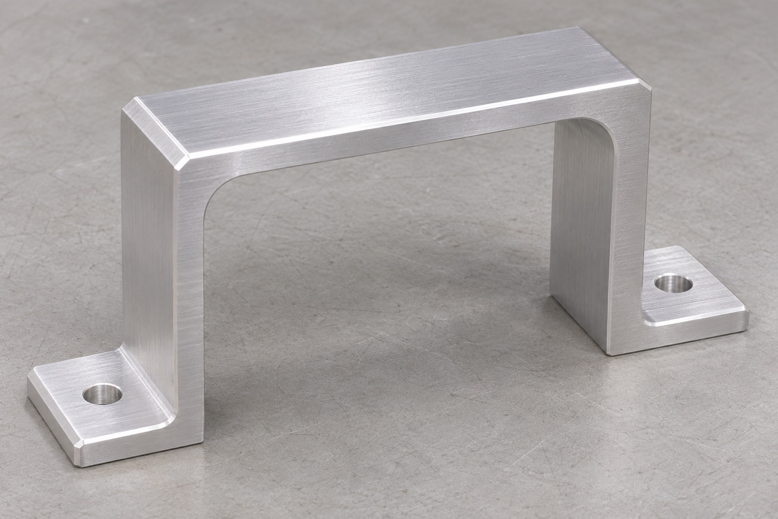
A cable bridge can provide a controlled route beneath an inert equipment assembly fixture while keeping the mounting interfaces accessible. The representative 6061 part here has a horizontal top beam, two downward legs and two outward feet. One plain vertical mounting hole passes through each foot. The arch is open underneath and through the front and rear; it is not a closed housing or a pressure passage. Precision aluminum CNC milling starts with the relationship between the feet and the opening, not only the visible arch. This guide does not specify a patient-connected infusion component, electrical safety protection or a validated pump accessory.

Identify where the bridge is meant to seat
Specify whether both foot undersides share a common mounting reference and how that requirement is evaluated. A single overall-height dimension does not establish the condition of both seating faces. Identify the contact areas, permitted edge breaks and any relief around the mounting holes. If the fixture base provides separate support pads, include those interfaces in the design review. Do not use bolt tightening to force a visibly distorted bridge into conformity. The drawing should explain the required free-state condition and, where applicable, the installed condition separately. This distinction helps prevent an apparently secure assembly from concealing an incorrect relationship between the two feet.
Define the cable envelope without claiming strain relief
The arch opening needs a defined clear width, clear height and depth for the intended dummy routing envelope. Review entry and exit edges, cable bend allowance and access for assembly. Do not assume that a cable passing through the opening establishes an acceptable bend radius or abrasion condition. Those requirements depend on the approved cable and system design. This part does not automatically provide retention, electrical isolation or strain relief merely because it resembles a protective bridge. Use a drawing-controlled inert envelope during fixture planning, and state whether any edge or surface condition needs a specific acceptance criterion beyond the ordinary external profile dimensions.
Specify 6061 stock and the finishing stage
Identify the alloy, required temper or supply condition, stock form and material records in the RFQ. The name aluminum does not define a permitted substitute. Include the required final surface condition, and resolve whether any coating or treatment is included before dimensions and inspection stages are agreed. A finish may affect mating interfaces or require masking, so it belongs in the manufacturing review rather than in an informal note after machining. Do not promise corrosion resistance, insulation or cleaning compatibility solely from an alloy designation or an attractive surface. The actual application and approved finish specification determine what evidence is needed for those claims.
Review arch accessibility during DFM
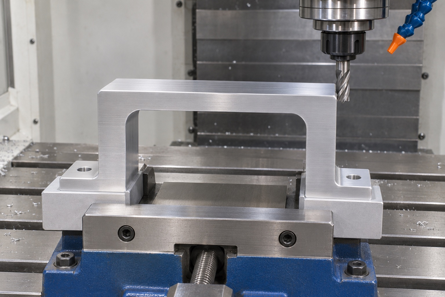
The open arch can often be approached from the side or underside, but the real tool path must be checked against the beam, legs and workholding. State allowable internal corner radii and verify clearance where the cable envelope approaches the opening corners. A square model corner is not permission to leave an arbitrary large radius. Nor should a supplier remove additional beam or leg material simply to make a standard cutter reach. Resolve any tool-access limitation before programming. This DFM review is especially useful for custom medical fixture parts because small changes to an apparently simple opening can alter the relationship between routing clearance and mounting stability.
Establish mounting references before final arch finishing
Choose a machining sequence that produces recoverable references and leaves sufficient material for stable clamping. Roughing the opening may change how the blank is supported, so plan which surfaces remain available for later operations. Document how the second setup recovers the approved mounting reference. A convenient rough stock face should not silently replace a drawing datum. Actual cutter choice and cutting conditions depend on the machine, tooling and geometry. The process plan should make the reasoning visible without claiming that a particular sequence guarantees flatness or accuracy for every bridge. Final conformity still depends on the manufactured part and the specified inspection method.
Hold the bridge without pulling the feet together
Workholding should resist machining forces without imposing an unapproved shape on the finished component. Review clamp locations on the beam and feet, jaw support beneath the blank and access for the arch cutter. Avoid treating a gap between a foot and fixture support as something that can always be eliminated with more clamping force. Clean support contacts before reseating, protect completed faces and record any special fixture conditions. After release from workholding, inspect the state required by the drawing. A dimension measured while the part is heavily constrained may not describe the free-state geometry that the receiving fixture will actually encounter.
Separate mounting-hole requirements from opening clearance
Each foot has one plain vertical through-hole. Specify the hole size, location and relationship to the mounting faces, plus the permitted entrance and exit edge treatment. There are no hidden threads or screw-head recesses in the representative geometry. Confirm that the selected fastener reference has the necessary access without changing the component to suit an unapproved screw. Hole conformity and arch clearance are separate acceptance questions. A bolt passing through both feet cannot prove the opening height, foot coplanarity or local edge condition. Include both sides of each hole in the deburring and visual inspection plan so the fixture base does not conceal remaining damage.
Inspect the opening and both feet in a defined state
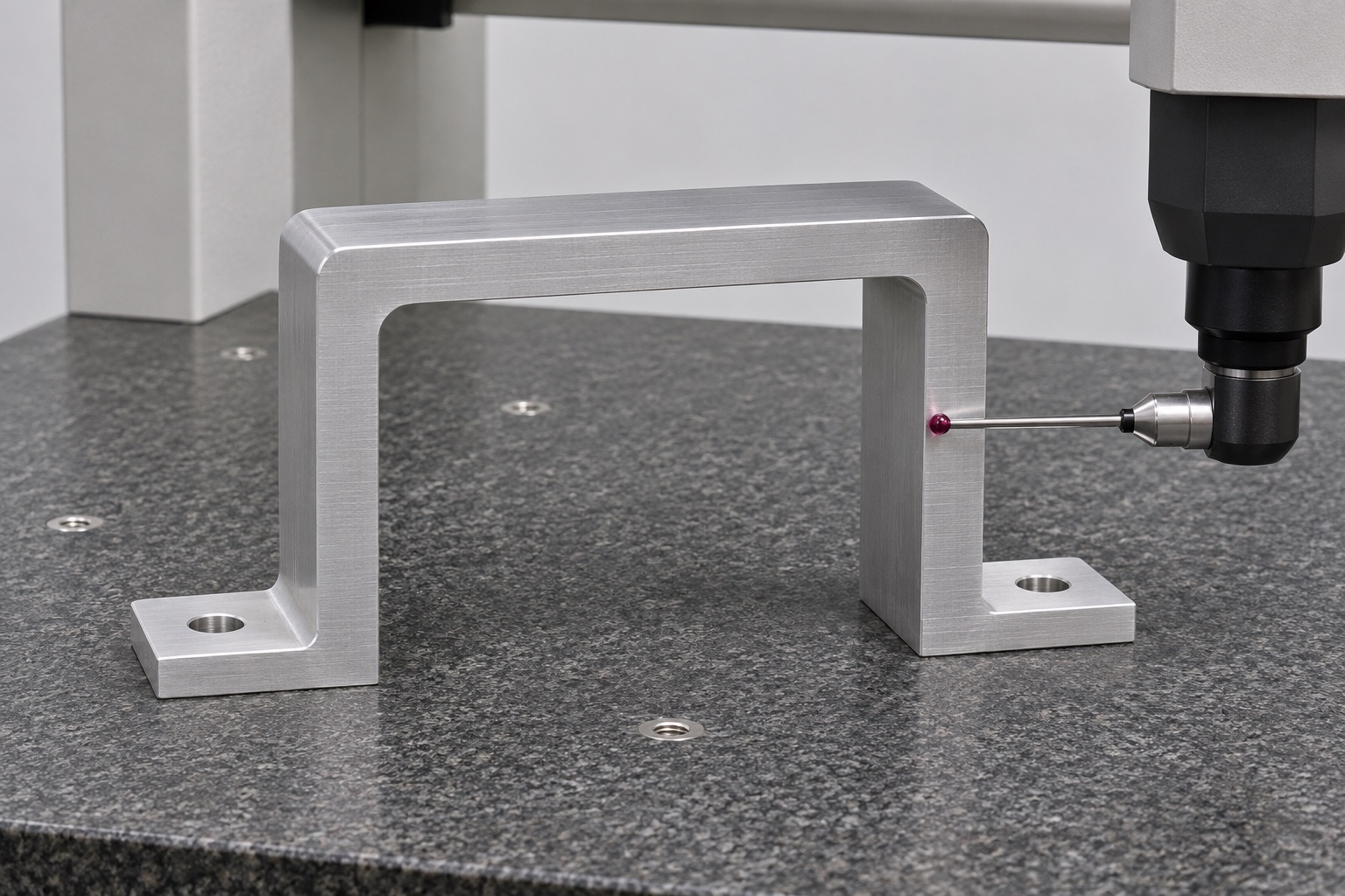
Map the drawing requirements to suitable measurements: foot seating condition, overall height, beam thickness, arch width and height, hole locations and any specified profile controls. Document the supporting surface and alignment used for each relationship. Do not report a single caliper opening measurement as evidence for the full arch profile. Coordinate measurement or other methods may be appropriate depending on access, tolerance and uncertainty. Record actual values for a first article and identify any requirement that cannot be evaluated with the proposed equipment. A measurement plan should establish how decisions will be made, not merely list instrument names without explaining what they measure.
Use dummy cable routing as a supplementary check
Assemble the bridge on an inert base with an approved cable-envelope reference or an unpowered dummy. Observe entry clearance, visible contact and fastener access under the specified condition. Do not pull on a cable to invent a retention or strain-relief test, and do not connect the arrangement to a functioning infusion pump. Any operational loading, electrical safety or cable-life requirement needs its own approved procedure and evidence. Retain the dummy reference revision and the observation record. If the assembly appears to fit only after forcing the feet down, investigate the geometry rather than treating successful fastening as proof that the bridge meets every drawing requirement.
Protect the arch edges through cleaning and packing
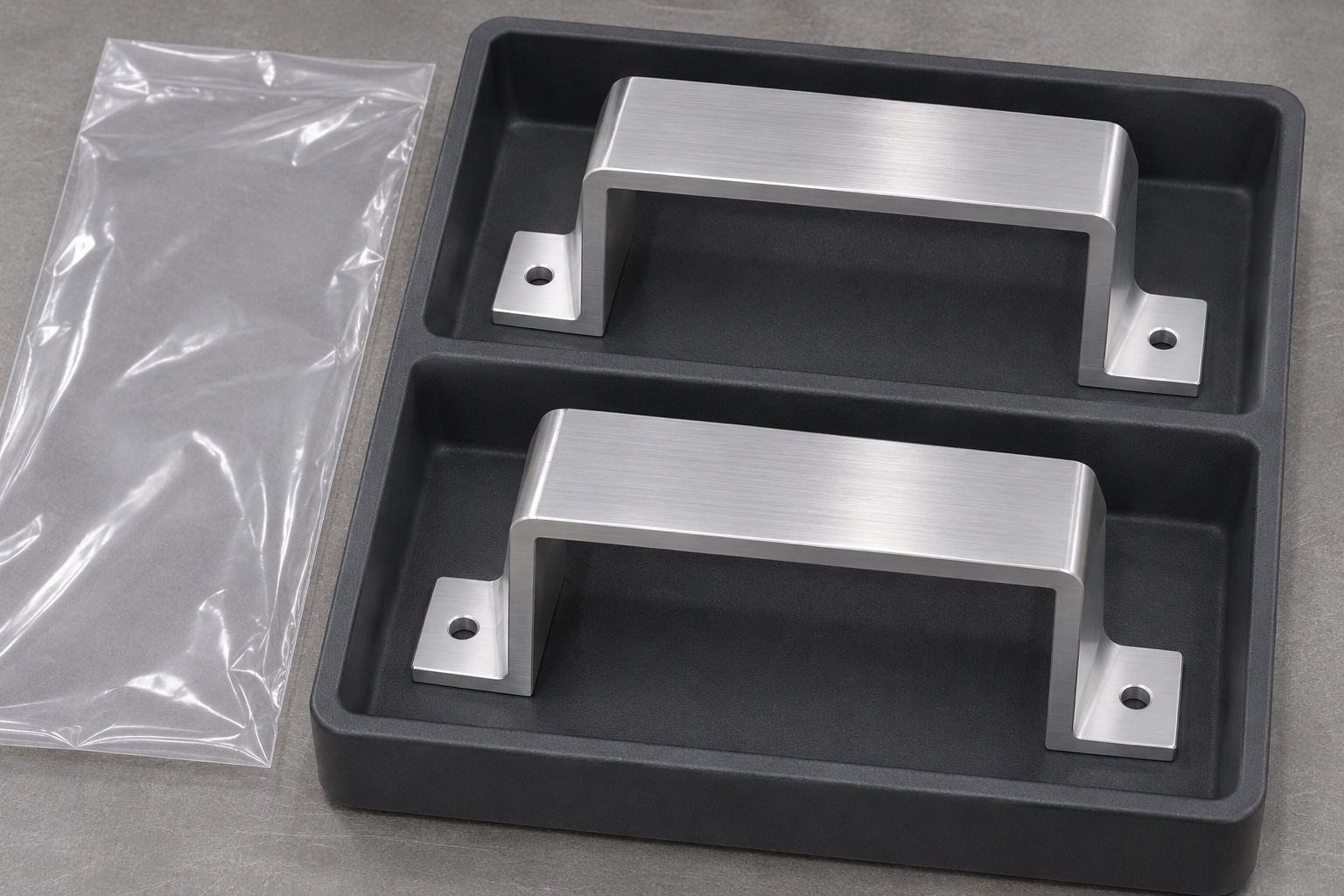
Agree the cleaning method, drying condition and handling requirements before release. Remove loose chips from the arch corners and mounting holes, and confirm the permitted condition of edges that face the cable envelope. Packaging should protect foot undersides and beam surfaces without wedging the arch into an artificial shape. Avoid loose protective material that can remain in the opening. Label the package with the part and drawing revision linked to the required inspection records. A clean-looking aluminum bridge in a sealed bag is not evidence of sterility, validated residue removal or suitability for clinical use. State only the outgoing manufacturing condition actually specified and documented.
Request a quotation around measurable bridge requirements
Provide the released drawing and model, 6061 supply requirements, quantity, surface finish and required documentation. Highlight the shared foot reference, free-state inspection condition, arch envelope and mounting-hole definition. Include the dummy routing check only if it is requested, and distinguish that observation from dimensional acceptance. Ask the supplier to resolve internal radii, clamping access and inspection limitations during DFM. For low-volume CNC milling, preserve approved fixtures and first-article methods so repeat orders are evaluated consistently. A precise RFQ helps compare manufacturing proposals without confusing attractive photographs, generic machining tolerances or the medical setting with evidence that the complete assembly has been validated.
FAQ
Is the cable bridge a patient-connected infusion part?
No. This guide covers an inert assembly-fixture component. Patient-connected, operational and electrical safety requirements require a separately approved design and evidence.
Does a cable passing through the arch prove clearance is acceptable?
No. Define the cable envelope, edge condition and any bend requirements. A simple pass-through observation cannot establish abrasion life, retention or strain relief.
Can fastening correct noncoplanar bridge feet?
Fastening can conceal distortion. Evaluate the specified free-state condition and any separate installed condition instead of assuming that tightened screws prove the drawing requirements.
Are the mounting holes threaded?
No. This geometry has two plain vertical through-holes, one per foot. Threads, counterbores and additional holes require an approved drawing change.
Must internal arch corners be perfectly square?
Not automatically. Define allowed radii and the required clear envelope. Review tool accessibility before accepting a radius that could interfere with the intended routing.
What should a first-article report include?
Identify drawing revision, material, part state, reference alignment, methods and actual results for feet, opening, beam and holes, plus any approved supplementary dummy check.

tanghangyun@oemach.com