
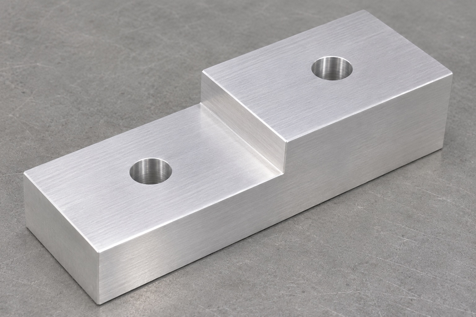
Define the two-level support without airflow claims
A stepped riser can position an inert portable spirometer reference in a development fixture. The representative 6061 part is a rectangular solid with a raised land over half its length, one shoulder between the high and low planes, and two plain vertical through-holes, one on each level. It has no airflow passages, electronics or hidden pockets. Precision CNC milling should preserve the relationship between support height and mounting geometry. This guide does not establish spirometer accuracy, respiratory performance or suitability for an operating medical device. Real use would require separate design approval and acceptance evidence beyond a machined block that visually resembles a plausible fixture support.

Identify which plane actually supports the reference
Request the inert reference envelope and the intended assembly sequence. The design owner should identify whether the high plane, low plane or another defined surface establishes support. The second level may provide clearance rather than contact, and that distinction changes the meaningful drawing requirements. Do not assume that both levels must touch merely because both are machined. Define the fastener access and any needed clearance at the shoulder. A matching model helps communicate these relationships, but the drawing must state tolerances and acceptance. This avoids a supplier manufacturing two attractive flat planes while misunderstanding which one controls the position of the dummy spirometer assembly.
Use a common reference for both height levels
Relate the high and low planes to an approved seating reference rather than dimensioning each from unrelated rough stock surfaces. Distinguish overall heights from their difference and from any geometric orientation requirements. Two individual height readings do not automatically establish the required support condition across each surface. The inspection plan should explain how the reference is recovered and where measurements are taken. Avoid an informal instruction to make the step exact without defining what is evaluated. A common reference strategy makes the relationship reviewable and reduces ambiguity when the same low volume aluminum component is ordered again with a different raised-land length or mounting arrangement.
Define shoulder position and the internal transition
The vertical shoulder has a location and an internal transition where it meets the lower plane. Review the feasible cutter path against the actual mating envelope. An ideal sharp CAD corner is not permission to hide an uncontrolled radius or add a relief without approval. If clearance is needed, the drawing should show it. A reference assembly can clear the high plane while still interfering at the shoulder root. The supplier needs to understand whether the shoulder locates the dummy or simply separates two support levels. These decisions should be resolved before CAM programming, not discovered after a finished riser is forced into an assembly that was never fully defined.
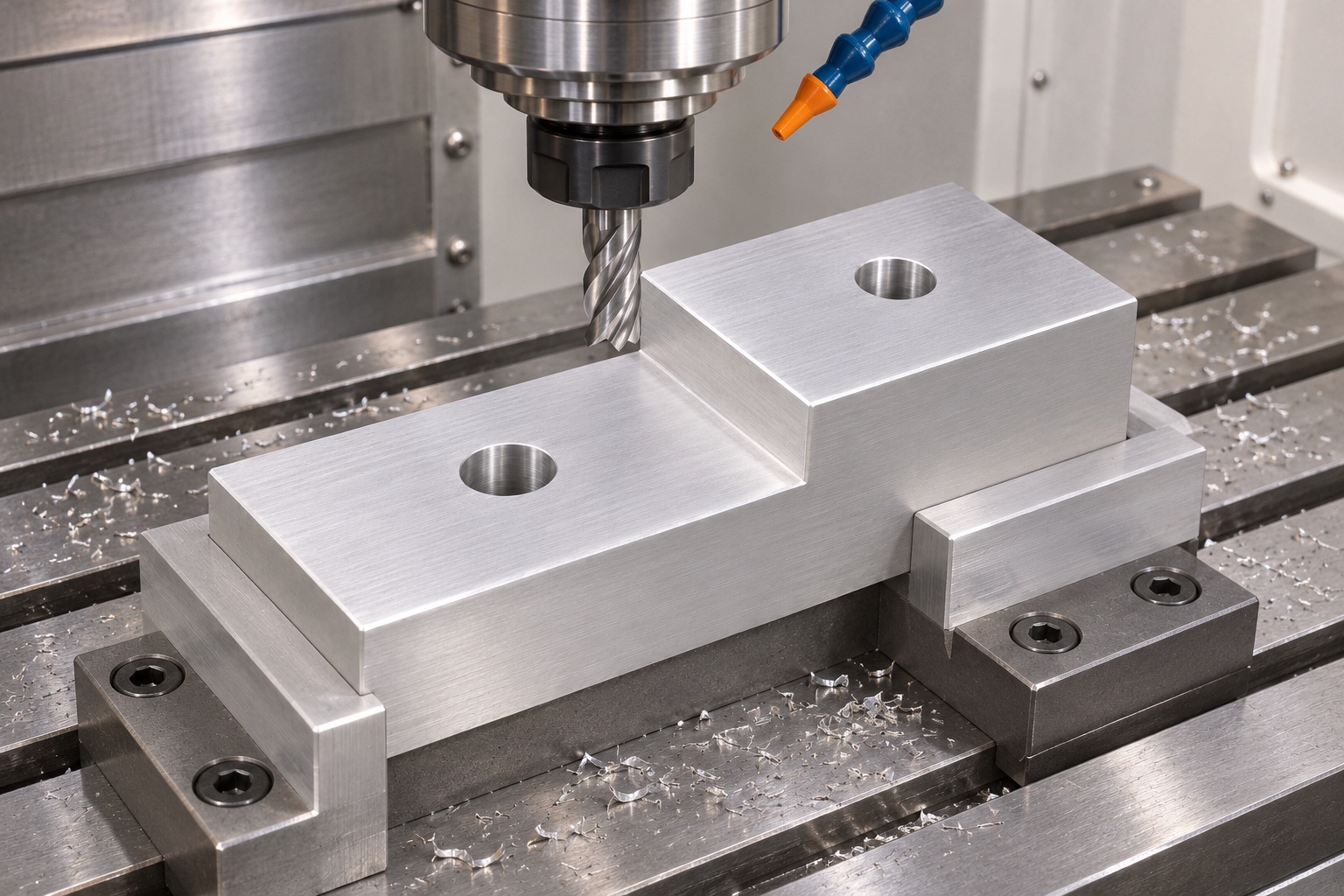
Specify 6061 material and the final surface condition
State the aluminum designation, temper, stock form and required records in the RFQ. Confirm substitutions before manufacture rather than assuming every aluminum block is equivalent. Define the approved finish, including whether the part remains bare machined or receives a separate treatment. If anodizing is requested, clarify masking and the dimensional acceptance of treated interfaces. A finish description does not independently establish cleaning-agent compatibility, biological safety or a service life. Maintain material and revision identity through the traveler and final package. The supplier should quote documented manufacturing work, not infer a medical qualification from the name of the equipment that the inert fixture represents.
Plan roughing around the raised land
Review the amount of material removed from the lower region and how the raised land remains supported. Leave appropriate finishing allowance where the process requires it. Clamp on stable areas that do not obstruct the shoulder tool path or damage final support planes. A suitable support fixture should be reviewed with the actual stock and proportions. Do not prescribe universal feeds or speeds from the part name alone. The route should record how references are established and recovered between operations. This helps repeat batches preserve the same support-height definition rather than silently inherit a different relationship from an improvised setup or a changed blank orientation.
Finish height and shoulder features coherently
Select the finishing sequence so the high plane, low plane and shoulder remain connected to the approved reference strategy. Review tool reach and access, especially near the internal transition. Do not manually blend the step root until a dummy happens to fit, because that can change the support or locating relationship. Inspect the finished component after release from machining workholding in the state required by the drawing. If material movement or reseating affects the relationship, investigate the process rather than relying on clamping force to restore nominal geometry temporarily. The objective is a measurable component condition, not a visually square step seen only while restrained on the machine table.
Keep the two mounting holes distinct and inspectable
The representative block has one plain through-hole on each height level. Their different entry heights do not authorize different undocumented thread or recess features. Specify diameters, locations and edge conditions separately from the support heights. Ensure tool exits and underside edges remain accessible for inspection. A long screw that can pass through both an assembly and the block does not prove the mounting pattern location. If a fastener-head recess is required later, update the drawing and process plan before cutting. The report should identify each hole so a discrepancy at one level cannot be concealed by an average result or a combined assembly observation.
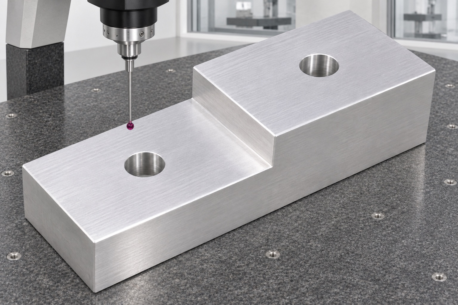
Measure more than the height difference
The first-article plan should cover relevant heights, plane conditions, shoulder position, hole pattern and their relationships to the seating reference. Select suitable methods for each requirement and record the support and alignment used. A depth or height gauge reading at one point cannot establish every surface characteristic. Report genuine measured results rather than nominal CAD values, and identify any access or uncertainty limitation before accepting the part. A representative guide does not establish production capability or achieved tolerance. Preserve the approved inspection approach for repeat orders so changes in measurement support do not masquerade as changes in the manufacturing process.
Limit the dummy check to a mechanical interface
An identified inert reference can supplement dimensional inspection by showing mounting access and visible interference at the shoulder. The check should not power a spirometer, involve breathing through a device or claim flow calibration. Define the reference revision and observation procedure, and avoid forcing the dummy onto an uncertain step. If an assembly can flex or clearance can hide a location error, note that limitation. A successful bench placement applies to one defined mechanical relationship only. Investigate drawing and measurement discrepancies before modifying the block; a convenient fit is not a substitute for the evidence needed to approve an operating medical instrument.
Protect both support levels through cleaning and shipment
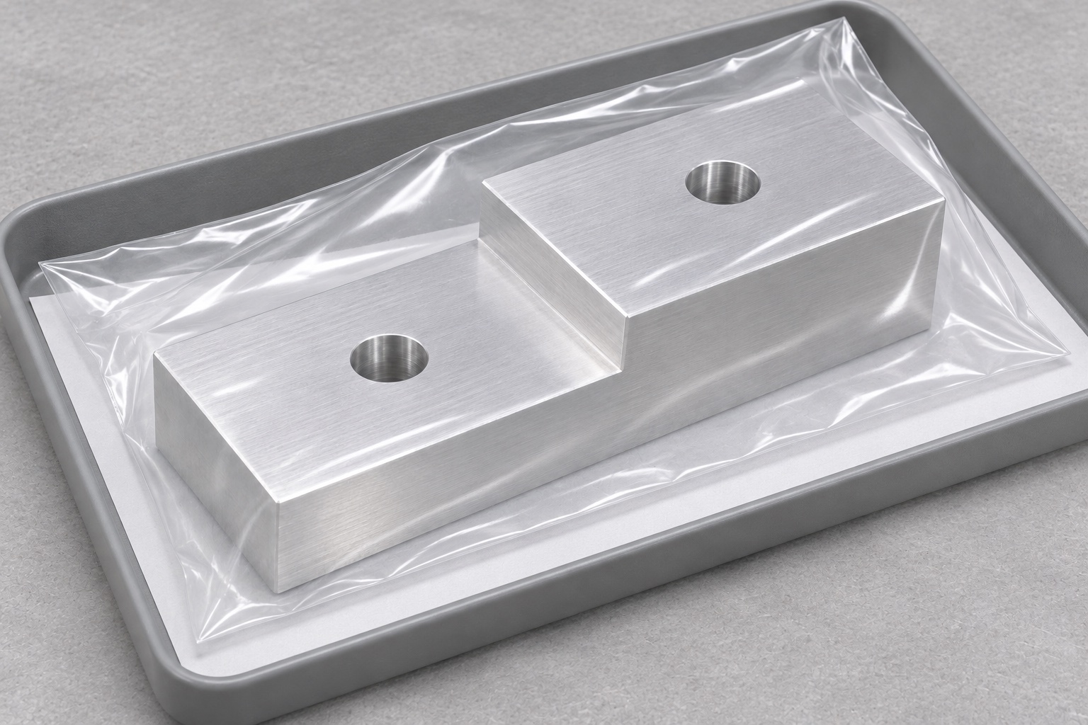
Agree cleaning, drying and final handling before packaging. Keep chips out of the shoulder root and through-holes without damaging the specified planes. Ordinary debris removal does not establish sterility or a numerical residue limit. Separate risers so the raised land cannot rub against neighboring components or loose hardware. Package identification should match the part and drawing revision in the actual inspection record. Protective film or inserts need approval if they could leave residue on a seating surface. Receiving inspection should still assess package integrity and the specified component condition rather than treating an intact outer carton as proof that both support levels remain conforming.
Prepare an RFQ for a controlled stepped fixture block
Provide the released drawing and model, 6061 designation and temper, quantity and inert fixture purpose. Identify the seating reference, two levels, shoulder geometry, mounting holes, finish, edges and inspection deliverables. Include the dummy definition only if a supplementary placement check is requested. Ask for disclosure of proposed substitutions or inaccessible measurements before manufacturing. Separate component machining from optional fixture development and any future medical-device qualification. A clear custom aluminum CNC quotation describes what will be manufactured and measured, making release decisions reviewable without inventing airflow accuracy, a clinical approval or a customer delivery that the component planning example cannot substantiate.
FAQ
Is the riser part of the airflow measurement path?
No. The guide concerns an inert mechanical fixture with no airflow passages. Flow calibration and operating-device use require independent definitions, evidence and approval.
Do both levels have to contact the dummy?
Only if the approved design requires it. One level may provide clearance, so the drawing must identify actual support and locating surfaces explicitly.
Why reference both heights to a common seat?
It makes their relationship consistently measurable. Separate readings from unrelated rough surfaces can leave ambiguity about the actual support condition or step difference.
Can an internal radius be added automatically?
No. Tool access and the shoulder transition must be reviewed. Any relief or changed radius requires approval when it changes the defined interface.
Are threads or counterbores included?
Not in this representative geometry. It has two plain through-holes, one per level. Additional fastener features must appear in a revised drawing.
What should a first-article report include?
Actual measurements for the specified heights, surfaces, shoulder and holes, together with reference alignment, methods, instrument identity and any evaluation limitations.

tanghangyun@oemach.com