
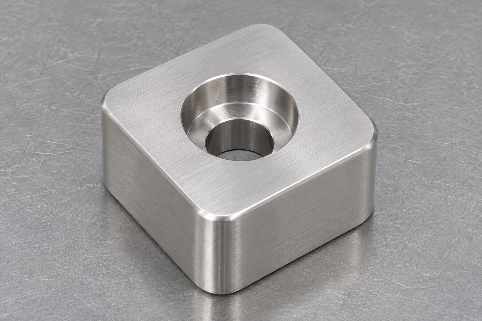
Define the corner foot and its actual interfaces
A corner foot can establish a repeatable support interface beneath an inert endoscope transport tray mockup. The representative part here is a short square 316L block with rounded outside corners, flat seating faces and one central counterbored through-hole. There are no side channels or concealed retention features. Precision CNC milling should begin with the surfaces that seat against the tray fixture and support base, not simply with the visible square outline. This guide does not define a clinical transport accessory, protective endoscope system or load-rated support. A real operating application requires its own approved design and acceptance evidence beyond a component manufacturing plan.

Separate seating geometry from external appearance
Identify which face contacts the tray fixture and which face rests on the supporting structure. Their required relationship should follow the actual assembly, including any specified flatness or orientation controls. Rounded outer corners may help handling clearance, but they do not establish how the foot seats. Do not apply tight tolerances to every cosmetic edge while leaving the functional faces undefined. A visually level block can still contact on an unintended high point. The drawing should distinguish thickness, seating conditions and profile requirements so the supplier can choose appropriate finishing and inspection methods instead of inferring function from an attractive rendered model.
Specify the mounting hole and screw-head recess
The central opening has two distinct features: a smaller through-hole and a larger cylindrical counterbore. Define their diameters, counterbore depth, shoulder condition and relationship to the seating references. A screw head that appears flush does not establish the recess depth or remaining wall thickness. The actual fastener definition should be reviewed with the block before release. Do not deepen the recess to accommodate a convenient screw without design approval. If the recess edge or shoulder is functional, state the permitted edge treatment explicitly. A generic instruction to drill the center cannot communicate the complete mounting interface or its inspection requirements.
Maintain 316L identity through the machining route
State the material designation, stock form, supply condition and required records in the RFQ. A small support component is not a reason to substitute another stainless grade without review. Keep the cut blank associated with its material identity and drawing revision through machining and inspection. If direct marking is not allowed on the part, identify the container or traveler instead. Material documentation supports traceability but does not independently establish corrosion life, cleaning compatibility or clinical suitability of the completed foot. Those claims require their own specified evidence. Confirm any proposed material or surface-treatment change before cutting rather than explaining it only after packaging.
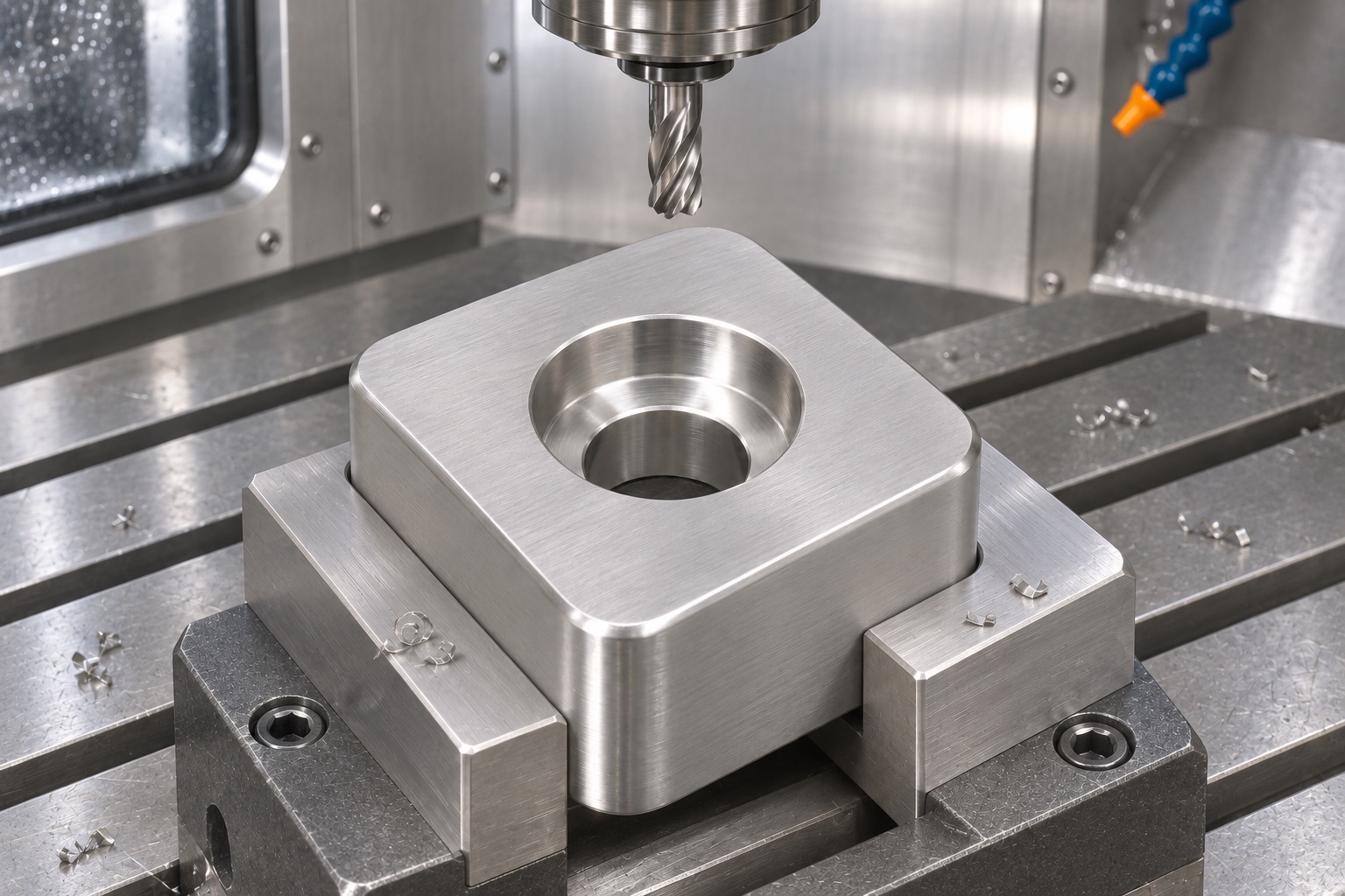
Establish useful references in the first setup
Prepare the blank with sufficient allowance for the finished seating faces and outside profile. Select stable support and clamp locations that leave the cutting path clear. The first operation should establish references that can be recovered during the opposite-face and counterbore operations. An arbitrary convenient rough edge should not become a hidden substitute for the drawing datum. Review tool reach, fixture clearance and the amount of material removed before programming the final passes. Actual cutting conditions depend on the selected tools, stock and machine; the name 316L corner foot does not supply a universal process recipe or an achieved accuracy claim.
Finish both seating faces without disguising form
The plan should explain how the second setup recovers the intended reference and protects the completed face. Remove chips from support contacts before reseating the workpiece, because a trapped fragment can change the apparent relationship between faces. Do not rely on clamping force to hide an unacceptable condition. Final inspection should evaluate the component in the state specified by the drawing after release from machining workholding. If the assembly uses several feet, define whether matching height or another group requirement is needed. That requirement must be approved rather than inferred from the assumption that every block in a tray kit should be identical in all respects.
Machine the counterbore with accessible exits
Select the hole-making and recess-finishing sequence for the actual geometry and requirements. The tool must reach the recess shoulder without leaving an unapproved transition, and the through-hole exit must remain accessible for edge inspection. A support fixture should not conceal retained chips or damage on the underside. Inspect the recess separately from the smaller hole instead of treating one passing fastener as proof of both features. If a tool cannot reach the specified shoulder or corner, resolve the requirement before manufacture. The approved drawing controls whether a transition radius is acceptable; a convenient cutter is not authorization to alter the fastener seat.
Preserve functional edges during deburring
Distinguish handling edges, hole entrances and the counterbore shoulder on the drawing. Removing a sharp edge should not enlarge the mounting hole or remove material from a screw-head seating surface without permission. Inspect both ends of the through-hole and the recess after loose debris is removed. Where small edges require magnification, agree a practical method and acceptance criterion. A smooth feel is not a complete inspection result. The supplier should record any inaccessible area before first-article approval rather than treating a general deburring instruction as evidence that every internal edge has been verified or that the component is suitable for medical handling.
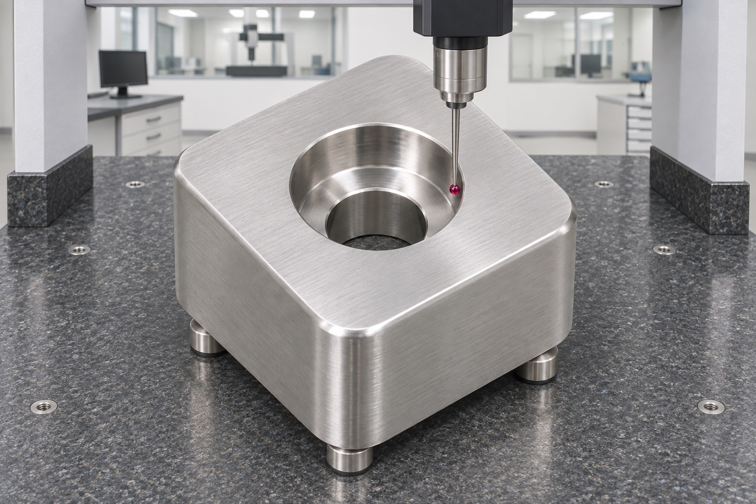
Build an inspection matrix for the complete foot
Map overall height, seating-face condition, hole location, hole size and counterbore geometry to suitable methods. Each measurement answers a different question, and a single caliper reading cannot establish every relationship. Identify the reference alignment and support used during inspection. Report actual readings from a manufactured component rather than copying CAD nominal values. A representative planning guide does not establish process capability, production yield or achieved tolerance. If the proposed equipment cannot evaluate a requirement credibly, disclose that limitation before agreeing shipment acceptance. For repeat low volume CNC orders, preserve the approved inspection setup so a changed method is not mistaken for changed component quality.
Bound the supplementary tray-fixture fit check
An inert tray corner and approved fastener reference can supplement dimensional inspection by showing assembly access and visible seating behavior. Identify the reference revision and the observation procedure. Do not load the fixture with an endoscope or claim transport protection from a simple bench assembly. The check does not establish load rating, stability during movement, cleaning validation or device compatibility. If the foot can be forced into contact by a screw, note that the assembly may hide a geometric discrepancy. Review the drawing and actual measurements before reworking a face merely because one dummy arrangement appears to rock or seat differently than expected.
Define cleaning and protective packaging separately
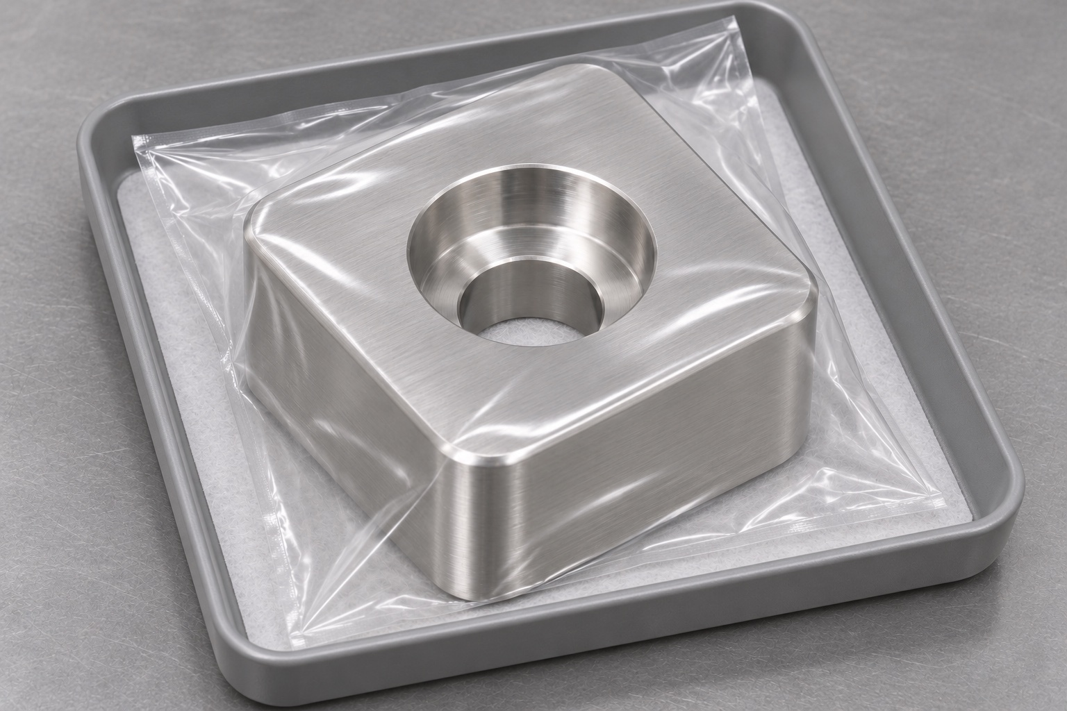
Agree the permitted cleaning agents, drying process and outgoing handling condition before final inspection. Ordinary chip removal does not establish a quantitative residue limit or sterility. Protect the counterbore and seating faces from loose packing material and metal-to-metal rubbing. Identify each package with the part and revision, linked to inspection records when required. Protective inserts must not leave unacceptable debris inside the recess. Packaging preserves a defined manufacturing condition; it does not qualify a foot for clinical transport. Receiving inspection should follow the actual purchase specification rather than treating a bright stainless surface and intact bag as complete evidence of compliance.
Prepare a drawing-based quotation for corner feet
Supply the released drawing, matching model, 316L requirements, quantity and inert fixture scope. Identify the seating references, fastener definition, counterbore details, edge conditions and required inspection documents. If a group of feet must meet an approved matching condition, state it explicitly and define the acceptance method. Include any requested dummy-fit observation separately from dimensional inspection. Ask for disclosure of substitutions or measurement limitations before manufacture. This gives custom medical equipment metal parts a measurable purchasing scope without inventing a clinical approval, load capacity or delivery record. A clear RFQ makes both the supplier's responsibilities and the buyer's release decision easier to review.
FAQ
Is the corner foot approved for clinical endoscope transport?
No. The guide concerns an inert tray fixture. Clinical transport, loading and device compatibility require independent design requirements, evidence and responsible approval.
Is a counterbore the same as the through-hole?
No. The larger cylindrical recess and smaller through-hole have distinct sizes and requirements. Their depth, shoulder and reference relationships must also be defined.
Can a flush screw head prove recess conformity?
No. Fastener appearance does not establish counterbore depth, remaining section or shoulder geometry. Use the inspection methods required by the drawing.
Must several feet always have matched height?
Only when the approved assembly requires it. State the group requirement and acceptance method rather than assuming identical individual dimensions guarantee the intended support condition.
Does routine cleaning make the foot sterile?
No. Chip removal, defined residue assessment and sterilization are separate requirements. Claim only the processes actually specified, performed and documented.
What supports a repeat CNC order?
Retain drawing and model revisions, material identity, approved setups, real first-article results, cleaning instructions and protective packaging requirements with the order record.

tanghangyun@oemach.com