
Define a support pocket rather than an optical surface
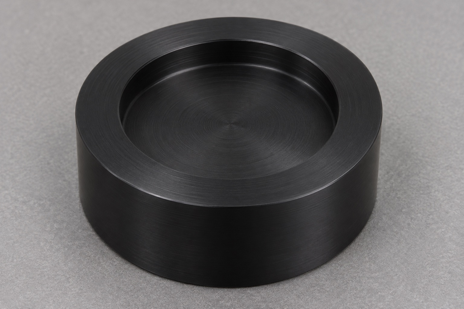
A lens blank support puck can provide a defined seat for an inert reference during ophthalmic fixture development. The representative part here is a short black POM-C cylinder with one shallow concentric circular pocket, a flat pocket floor and a broad annular rim. Its bottom is solid, with no vacuum passage, through-hole or side feature. This guide concerns mechanical seating on an unpowered bench. It does not specify an optical polishing tool, suction chuck or support approved for a real coated lens. Precision acetal machining should preserve the required pocket and seating geometry without implying optical quality, scratch resistance or compatibility with a clinical instrument.

Identify the reference blank and intended contact
Request the inert reference geometry and identify which area is meant to touch the puck. A flat pocket floor does not automatically match a curved lens surface, and an outside diameter alone does not describe the contact envelope. The design owner should decide whether the reference sits on the floor, rim or another explicitly defined interface. Do not introduce a compliant liner, adhesive or vacuum feature without approval. If the real application needs one, its geometry and acceptance requirements belong in a revised design. The supplier should quote the specified support component rather than assume how every ophthalmic lens blank will behave when placed in a circular recess.
Distinguish POM-C from an unspecified black plastic
State the required acetal copolymer designation, grade, color and stock documentation in the purchase order. POM-C and POM-H are different material designations, so a generic acetal label is not enough when the drawing requires one specifically. Black appearance does not identify the grade or prove a particular formulation. Keep stock identity associated with the traveler through turning and final handling. Confirm substitutions before cutting. The material specification supports traceable manufacture; it does not by itself establish suitability for coated optics, sample contact or a medical cleaning process. Those application requirements need their own defined evidence rather than an inference from color or polymer family.
Relate pocket position to the actual seating reference
The external cylinder may be useful as an alignment feature, but the drawing should identify which surface actually locates the puck in the fixture. Define the pocket diameter, depth and relationship to that reference separately. A concentric-looking recess in a photograph does not establish the specified location or direction. If the bottom face controls seating, its relationship to the pocket floor may also matter. Choose geometric requirements according to the actual assembly function and ensure the inspection setup can reproduce them. Avoid compressing diameter, position and floor condition into a vague instruction to make the part concentric and smooth without measurable acceptance criteria.

Plan turning around controlled polymer restraint
Select workholding for the actual stock diameter, wall remaining around the pocket and required surfaces. Avoid clamping force that distorts the cylinder into a condition that disappears after release. Soft jaws or another suitable support arrangement may be considered, with contact areas and tool clearance reviewed before cutting. Leave the material needed for the final operations according to the process plan. Do not prescribe universal speeds and feeds from the name POM-C alone. The approved route should account for the actual tool, stock, geometry and machine condition and remain documented so a repeat low volume acetal order can recover the same manufacturing references.
Finish the pocket floor and wall as separate features
The shallow recess includes a cylindrical wall, a flat floor and an internal transition. Specify the permitted corner radius instead of assuming an infinitely sharp intersection. The selected tool must reach the floor without damaging the wall or leaving an unapproved center feature. A facing operation may establish the floor, while the wall follows its own diameter and surface requirements. A smooth-looking recess does not prove the contact geometry or a particular optical finish. If a small tool mark is unacceptable for the intended inert reference, define a measurable surface requirement and inspection method rather than relying on a general request for mirror-like plastic.
Preserve the rim and solid bottom through the sequence
The representative puck has an annular top rim and a solid bottom beneath the shallow pocket. Do not add a central drill-through, vacuum groove or side port to simplify workholding or cleaning. Review the remaining section and final thickness against the actual drawing before selecting a second operation. The bottom face must be finished and inspected without damaging the completed pocket. If support changes between setups, document how the required locating references are recovered. A fixture that grips the rim may hide a distorted condition, so final acceptance should follow the specified released component state rather than only the shape seen while it remains restrained on the lathe.
Use low-force inspection for pocket and seating relationships
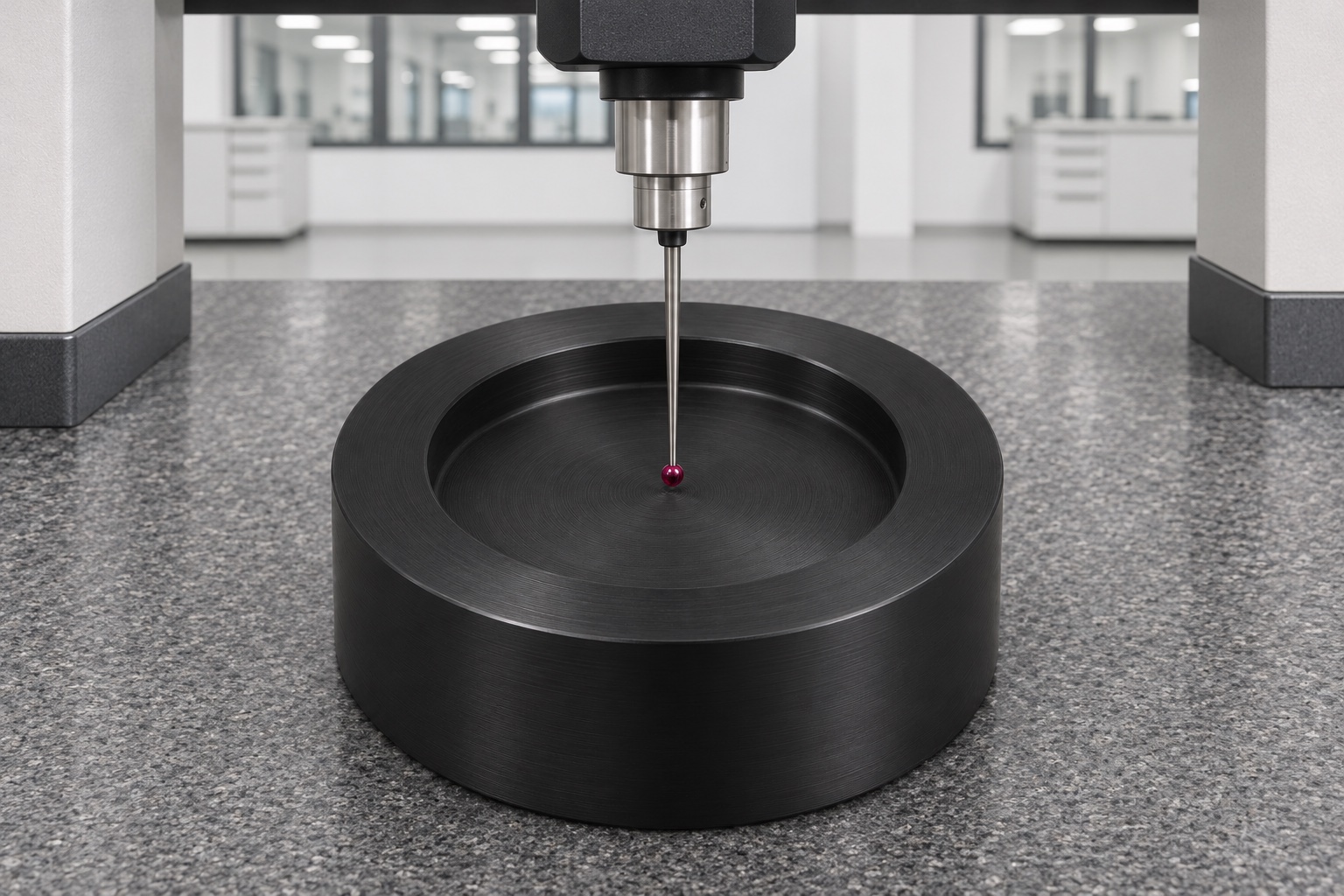
Map diameter, depth, floor condition and location to suitable methods, recognizing that each measurement answers a different question. Review support and contact force so the inspection setup does not deflect the polymer or damage the finished surface. A depth reading at one point does not automatically establish the entire floor condition, and a diameter gauge does not prove position. Record actual results and identify the measurement alignment. Environmental or conditioning requirements should be stated when the drawing or purchase specification calls for them. Do not infer capability from one part or report nominal CAD values as actual measurements in a first-article inspection record.
Control edges without creating an unapproved contact ring
Define the edge break around the outside diameter and pocket entrance. Manual rounding can change where an inert reference first touches, especially when the design relies on a narrow annular area. Remove loose polymer debris using an approved method and inspect the floor-to-wall transition for retained chips. Avoid judging a surface only by touch when that handling could introduce marks or contamination. The drawing should distinguish functional contact areas from noncritical handling edges. A polished appearance alone does not establish scratch-free performance on real optics, and the machining supplier should not claim lens compatibility without an application-specific acceptance procedure approved by the responsible design team.
Keep the supplementary seating check inert
An identified dummy blank can supplement dimensional inspection by revealing seating access or visible interference. The procedure should specify orientation and observation without pressure or unapproved coatings. Do not test with a valuable optical component simply because the puck looks smooth. If a dummy can rock, review its approved geometry and the measured pocket condition before changing the floor by hand. A successful bench placement does not establish optical centration, coating safety or compatibility with every blank shape. Its evidence applies only to the particular inert reference and bounded check, separate from the dimensional report and any future real-lens handling qualification.
Specify cleaning and individual protective packaging
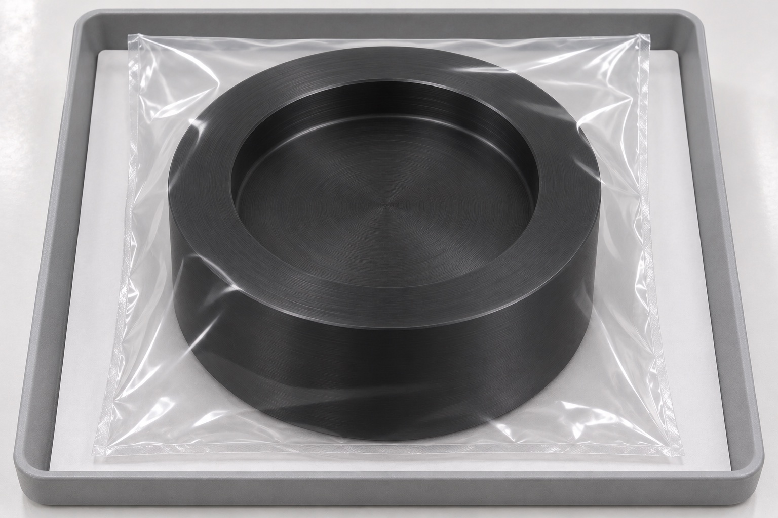
Agree the cleaning method, drying procedure and final handling requirements for the actual POM-C grade and fixture scope. Ordinary debris removal does not establish a quantified residue limit, sterility or suitability for coated lens contact. Keep abrasive particles and loose packing fibers out of the recess. Package each puck separately so the rim and floor do not rub against other parts. Identify the part and revision on the outer package, connected to the inspection record where required. Protective containment should preserve the inspected condition without implying a validated sterile barrier, and receiving inspection should still follow the actual purchase specification rather than the appearance of a clean bag.
Write an RFQ for a measurable acetal support component
Provide the released drawing and matching model, POM-C grade and color, quantity and intended inert fixture use. Identify the pocket definition, seating reference, permitted internal transition, edge conditions and inspection deliverables. Include the dummy blank definition if a supplementary seating observation is requested. Ask the supplier to disclose proposed substitutions or measurement limitations before manufacturing. Separate any future optical-contact evaluation from component turning and ordinary protective handling. This helps a custom optical fixture parts order remain technically clear: the supplier manufactures and measures a specified support puck, while application approval follows real evidence rather than a broad assumption about an engineering plastic.
FAQ
Is the puck an approved lens polishing or vacuum tool?
No. It is an inert mechanical support example with a solid bottom. Polishing, vacuum holding and operating-instrument use require separate designs and evidence.
Does black color identify POM-C?
No. Specify the exact material designation, grade, color and stock evidence. Appearance alone cannot establish polymer identity or authorize a substitution.
Can POM-H replace POM-C automatically?
No. They are distinct material designations. A proposed change must be reviewed against the drawing, process assumptions and intended fixture requirements before manufacture.
What defines the pocket beyond its diameter?
Depth, floor condition, internal transition and relationship to the actual seating reference must also be specified. One diameter reading does not establish the full interface.
Can a dummy blank prove scratch-free use on real optics?
No. A bounded inert seating observation does not establish coating safety, optical alignment or compatibility with every lens blank. Real-contact qualification requires its own evidence.
What should the RFQ contain?
Provide drawing and model revisions, POM-C grade and color, quantity, pocket and reference requirements, inspection methods, dummy definition, cleaning instructions and protective packaging scope.

tanghangyun@oemach.com