
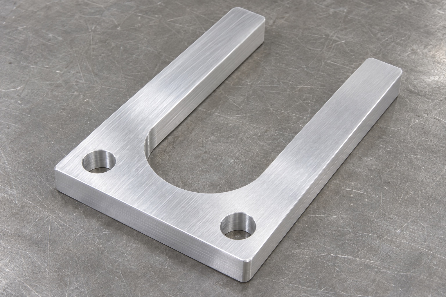
Define the fork as a mechanical fixture interface
A headset support fork can position an inert reference assembly during audiometer fixture development. This guide considers a thick flat 6061 aluminum U-profile with two straight prongs, a connecting base and two plain mounting through-holes in that base. The open central slot has a rounded root. It is a machined plate profile, not a bent sheet bracket. The scope is mechanical support on an unpowered bench, without a person or operating transducer. Precision CNC milling should preserve the approved contact and mounting geometry; it does not establish acoustic calibration, hearing-test accuracy or suitability for a clinical headset merely because the fixture is associated with audiometry.

Request the actual headset reference geometry
Ask the design owner to identify the inert mating assembly and the surfaces that may contact the fork. A generic headset outline does not define the intended support points, insertion direction or clearance. Decide whether the prongs locate a feature or simply carry a dummy envelope without constraining it tightly. The released drawing should express those decisions before the supplier selects tolerances. Do not assume that two visually similar headset references share the same interface. If a new reference changes the contact geometry, review the fork revision and inspection plan rather than adjusting the prongs informally until the new item can be placed between them.
Separate open-slot width from root clearance
The straight prong faces and the rounded slot root serve different geometric roles. Define the useful straight contact length, opening width and root profile independently where the assembly requires it. A dummy that clears the entrance may still interfere deeper in the slot. Conversely, an oversized root can remove material needed for the intended support geometry. Review the cutter's achievable path before accepting a model with an unspecified internal transition. If an extra relief is necessary, show and approve it on the drawing. The supplier should not add hidden clearance cuts or square-looking corners merely to make a nominal CAD assembly appear to fit.
Relate the mounting base to the contact faces
Choose references that reproduce the fork's actual seating and orientation on the fixture. Locate the two base holes and the open profile within that shared system. Hole size alone does not establish the position of the support faces relative to the fixture. Identify whether the fasteners only clamp the part or also participate in a locating scheme. Clearance must be distinguished from an intended close fit rather than inferred from the screw model. The inspection plan should recover these same relationships without forcing the prongs against a convenient gauge. This prevents a mounting pattern that passes inspection while leaving the headset reference in an unintended position.
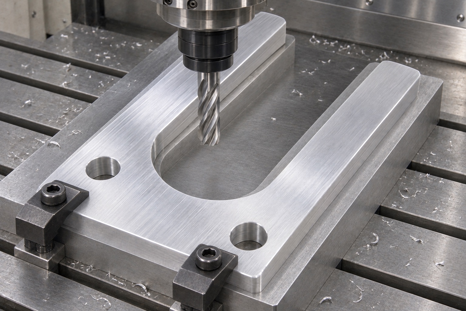
Specify 6061 material and finish before quoting
State the aluminum designation, temper, stock form and required records in the purchase specification. Any proposed substitution needs review before manufacture. Define whether the approved condition is bare machined or includes a separately specified surface treatment. If anodizing is requested, the design owner should address masking and how treated interfaces are evaluated. Do not infer chemical compatibility, patient-contact suitability or a particular service life from a finish description. For custom medical equipment aluminum parts, material identity and finish scope should stay traceable to the actual order. A small quantity does not remove the need to distinguish a documented supply condition from a generic aluminum label.
Rough the profile while keeping both prongs supported
Plan the workholding and removal sequence around the open U-profile. The prongs may become less supported as the central opening and outer contour approach final shape. Leave appropriate finishing stock and avoid concentrating clamp force on unsupported ends. A support fixture can help, but its contact areas and tool clearances must be reviewed. The correct route depends on the actual proportions, stock and machine, not on one universal feed or speed. Record how the blank is restrained and how the functional references are preserved between operations. This matters when a repeat small batch otherwise risks inheriting a different prong condition from an undocumented setup change.
Finish prong faces without treating restraint as straightness
The finishing strategy should generate the specified contact surfaces while protecting the base references. Do not use heavy restraint to force the prongs into the nominal spacing and then inspect only in that restrained state. Evaluate the required geometry after release from machining workholding, using the support condition stated in the inspection plan. Width at the entrance is not a substitute for checking the useful contact length or the specified direction of the prong faces. If the component changes after unclamping, review stock preparation and the process sequence before accepting repeated manual corrections that cannot be linked to a controlled manufacturing route.
Drill the base holes and retain edge access
The representative fork uses two plain circular through-holes in the connecting base. Threads, counterbores or inserts are not assumed. Select operations that meet the actual hole-size and edge requirements, with clear tool exits and accessible underside inspection. Identify the two holes separately in the report so their pattern cannot be hidden behind an average spacing value. Avoid damaging completed prong faces during a second setup for the base. If an assembly change requires a new screw-head recess or a different locating feature, revise the drawing and process plan before cutting. Small fastener changes can alter support and reference recovery as well as the visible hole geometry.
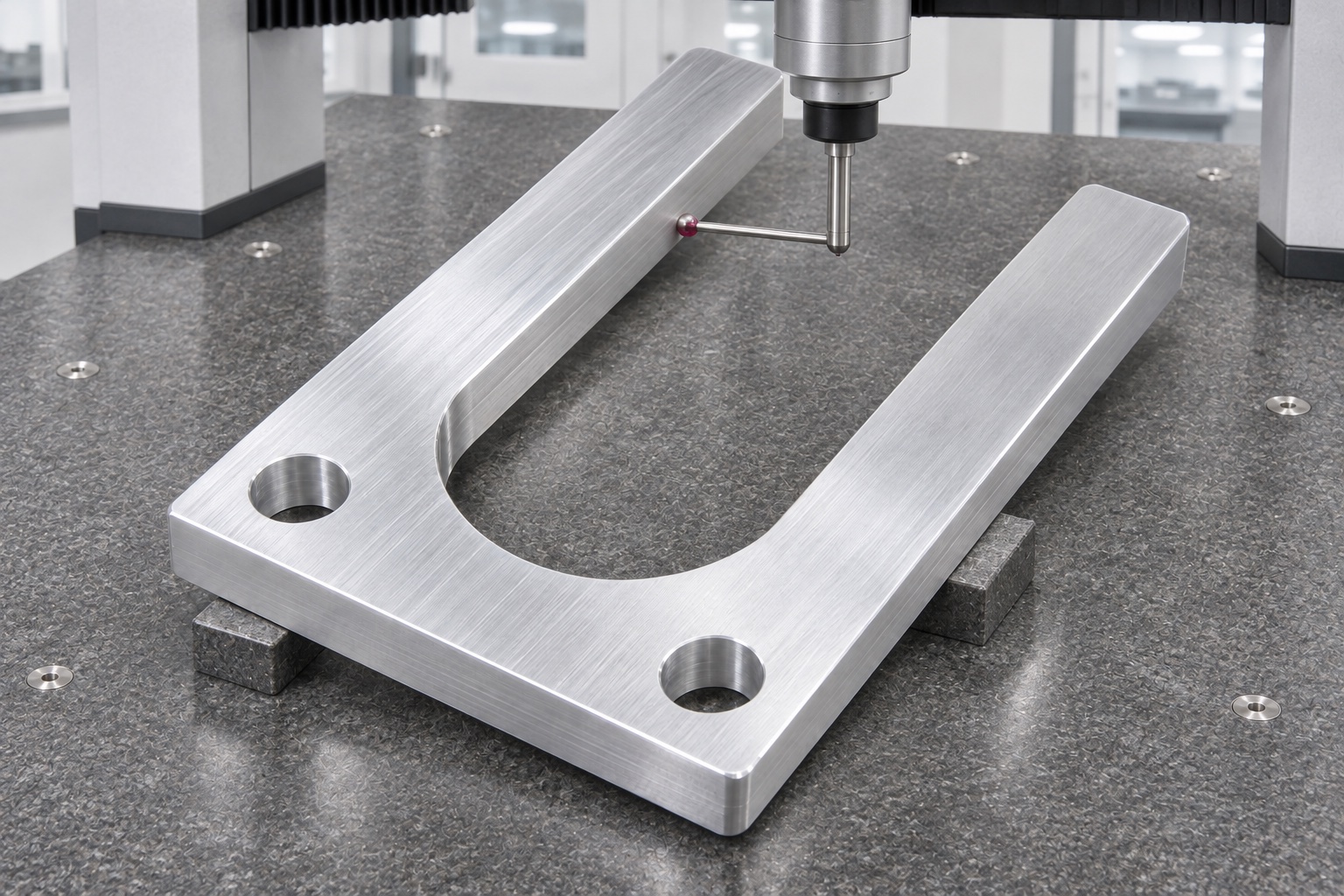
Control edges at the prongs and rounded root
Define edge breaks on the outside outline, prong tips and slot root without allowing uncontrolled rounding of the intended contact faces. A polished appearance does not establish the required contour. Inspect both sides and remove loose chips before judging a suspected edge defect. The transition between a straight wall and the rounded root should remain consistent with the approved drawing after finishing. If the design relies on a defined contact line, clarify whether an edge treatment changes that relationship. The machining supplier should not claim headset comfort or acoustic behavior from ordinary deburring; these are separate assembly and application questions requiring their own evidence.
Measure the fork in its specified free condition
A first-article plan should cover the mounting pattern, seating face, opening profile, prong spacing and required geometric relationships. Select suitable methods for each feature and record the reference alignment and support. Contact probing must not deflect the feature into apparent conformity. A noncontact method may be considered where justified, but it still requires an appropriate setup and evaluation. Actual readings belong in the report; nominal model values do not establish achieved accuracy. Keep dimensional results separate from visual observations and an optional dummy placement check. The objective is reviewable evidence for a defined machined fork, not a capability claim inferred from one appealing inspection photograph.
Bound the dummy placement check and outgoing handling
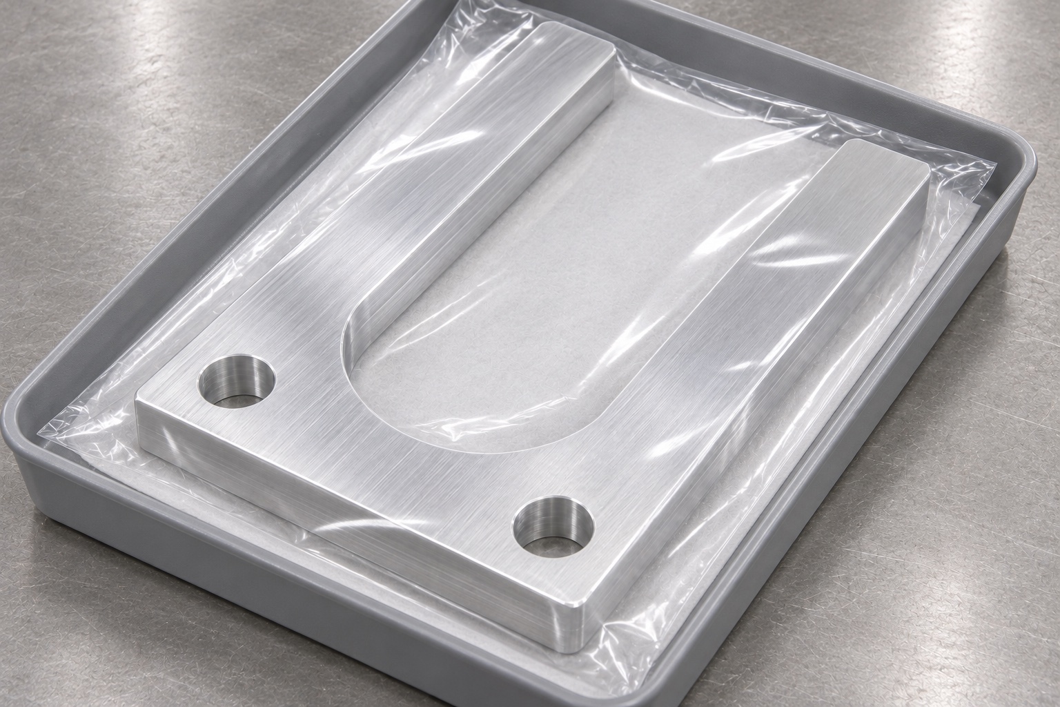
Use an identified inert reference for any agreed placement observation. Check access and visible interference without powering a transducer or involving a person. A successful placement does not demonstrate acoustic calibration, transducer force or clinical suitability. If the fixture can flex or hide a profile error, record that limitation. After the specified cleaning and drying process, protect the prongs from bending loads and metal-to-metal contact during packaging. Labels should identify the part and revision without unsupported sterile claims. Receiving inspection should follow the agreed requirements rather than treating an undamaged carton as proof that the free-state opening remained unchanged throughout transport.
Prepare a complete support-fork machining RFQ
Supply the released drawing, matching model, 6061 designation and temper, quantity and inert fixture purpose. Identify mounting references, prong contacts, root clearance, finish, edge conditions and required inspection records. Include the dummy definition if a supplementary placement check is part of the order. Ask for disclosure of tool-access or measurement limitations before manufacture. Separate the price of component machining from any development fixture or special inspection tooling. This gives a low volume CNC milling quotation a clear technical scope and avoids turning a representative support geometry into a claim about the performance of an audiometer, a headset or a medical testing procedure.
FAQ
Is the fork an acoustic calibration component?
Not in this guide. It is an inert mechanical fixture example. Acoustic calibration and hearing-test suitability require separately defined equipment, procedures and supporting evidence.
What geometry does the example use?
A thick flat U-profile with two straight prongs, a rounded slot root and two plain mounting through-holes in the connecting base. No inserts or threads are assumed.
Why define the rounded root separately?
Entrance width does not establish deeper clearance or the straight-to-curved transition. The root must match the approved mating geometry and feasible cutting process.
Can the prongs be measured while forced against a gauge?
Only if a specified inspection condition explicitly requires that restraint. Otherwise the setup must avoid forcing the component into apparent conformity.
Is anodizing automatically part of the order?
No. Treatment, masking, dimensional effects and inspection sequence require separate approval. The drawing may instead specify a bare machined condition.
What should accompany a quotation request?
Provide the drawing and model, material and temper, quantity, contact and mounting definitions, inert reference, finish scope, inspection deliverables and protective packaging requirements.

tanghangyun@oemach.com