
Start with the two-slot attachment interface
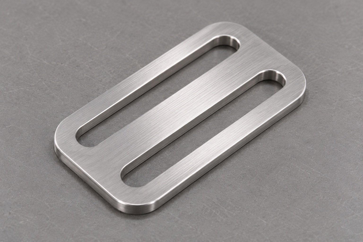
A belt-clip anchor plate can connect a defined attachment element to an inert Holter recorder fixture. The representative geometry here is a thin rounded rectangular 316L plate with two parallel oblong through-slots and a solid web between them. Both slots run along the long direction of the plate. There are no circular holes or hidden retention features. Precision CNC milling should begin by defining how the mating element passes through those openings and which surfaces establish its position. This guide concerns mechanical fixture development, not a patient-worn attachment, released device accessory or claim that a recorder will remain secure during real use.

Distinguish slot width from the complete slot profile
Width alone does not describe an oblong opening. Define the straight portions, semicircular ends, overall length and relationship between the two slots. State whether a profile control or another drawing requirement governs the transitions. A gauge that passes through the middle may miss a mismatch at an end radius, while a correct overall length may conceal an incorrect straight segment. The mating element's approved shape should guide these decisions. Avoid replacing the functional contour with a convenient cutter path before drawing review. The supplier needs to know which dimensions support actual fixture fit and which simply describe the plate's external appearance.
Choose plate and pattern references deliberately
Identify the face that rests against the fixture as a suitable primary reference when that matches the intended assembly. Define the long direction and pattern origin from controlled features rather than an unfinished blank edge. The two slots must relate to the same references so their spacing is evaluated consistently. Distinguish a slot centerline from a physical locating surface, because the inspection method must recover the specified relationship. An external rectangular outline is not automatically the best datum for every design. Resolve the drawing and measurement approach together before programming, especially when the mating clip can move within intentional clearance and obscure a pattern-location error.
Specify 316L stock and its traceable condition
The RFQ should state the material designation, supply condition and required documentation. A generic stainless description does not authorize a different grade merely because the finished plate looks similar. Keep the blank identity linked to the job traveler and drawing revision through machining and inspection. Confirm substitutions before cutting rather than documenting them only after shipment. If a surface treatment is required, define it separately and review its relationship to final acceptance. Material records establish the basis for material identity; they do not independently approve skin contact, attachment durability or compatibility with a medical recorder. Those application decisions remain outside this inert-fixture machining guide.
Preserve support while opening the first slot
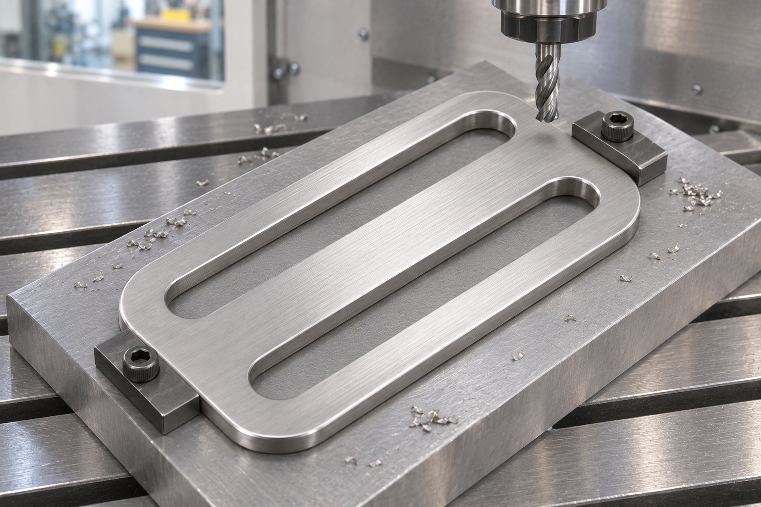
The remaining web and outside frame need adequate support as the openings are machined. Review the order of material removal, the clamping locations and the point at which each slot becomes a through-feature. A support plate may help, but it must not obstruct the cutter exit or trap debris against the finished underside. Leave suitable material for finishing passes when the process requires it. Do not prescribe one universal cutting recipe for all 316L plates: actual tool engagement, reach and setup stiffness matter. Document the chosen route so a repeat small batch does not quietly use a different unsupported cutting sequence near the thin central web.
Match cutter access to the rounded slot ends
Review the tool diameter and approach path against the released end geometry. The cutter must reach the required profile without striking clamps or relying on an impossible sharp internal corner. A roughing operation can leave material for the final contour, with the finishing strategy selected for the actual machine and tool. Do not enlarge the slot ends simply to accommodate a convenient cutter. If access or tool geometry makes the specified contour impractical, ask for clarification before manufacturing. The approved drawing, rather than an attractive CAM simulation, determines whether a proposed slot-end radius and transition are acceptable for the defined attachment interface.
Inspect the web in the released component
Measure the slot pattern and the central web in the component state required by the drawing, not only while the plate is clamped flat. Restraint can hide a changed form or hold the two slots in an apparently favorable relationship. The inspection setup should define support without forcing conformity. Check thickness and the specified geometric condition separately from slot width. A visually even web does not establish all positional or form requirements. Record actual readings and the method used. If a thin area cannot be measured credibly with the proposed instrument, resolve the limitation during first-article planning rather than reporting a nominal model value as a measured result.
Define edges where attachment elements pass
The through-slots have entry and exit edges that may interact with an inert clip or strap reference. Specify the permitted edge break and distinguish it from the slot's functional profile. Removing an edge defect must not become uncontrolled enlargement of the opening or thinning of the web. Inspect both sides after chip removal, including the curved ends and the transition to the straight walls. Magnification or another suitable method may be agreed when small features require it. A smooth touch is not a complete inspection record, and the machining supplier should not infer wearable comfort or strap-life performance from a basic deburring requirement.
Build a profile-based first-article inspection plan
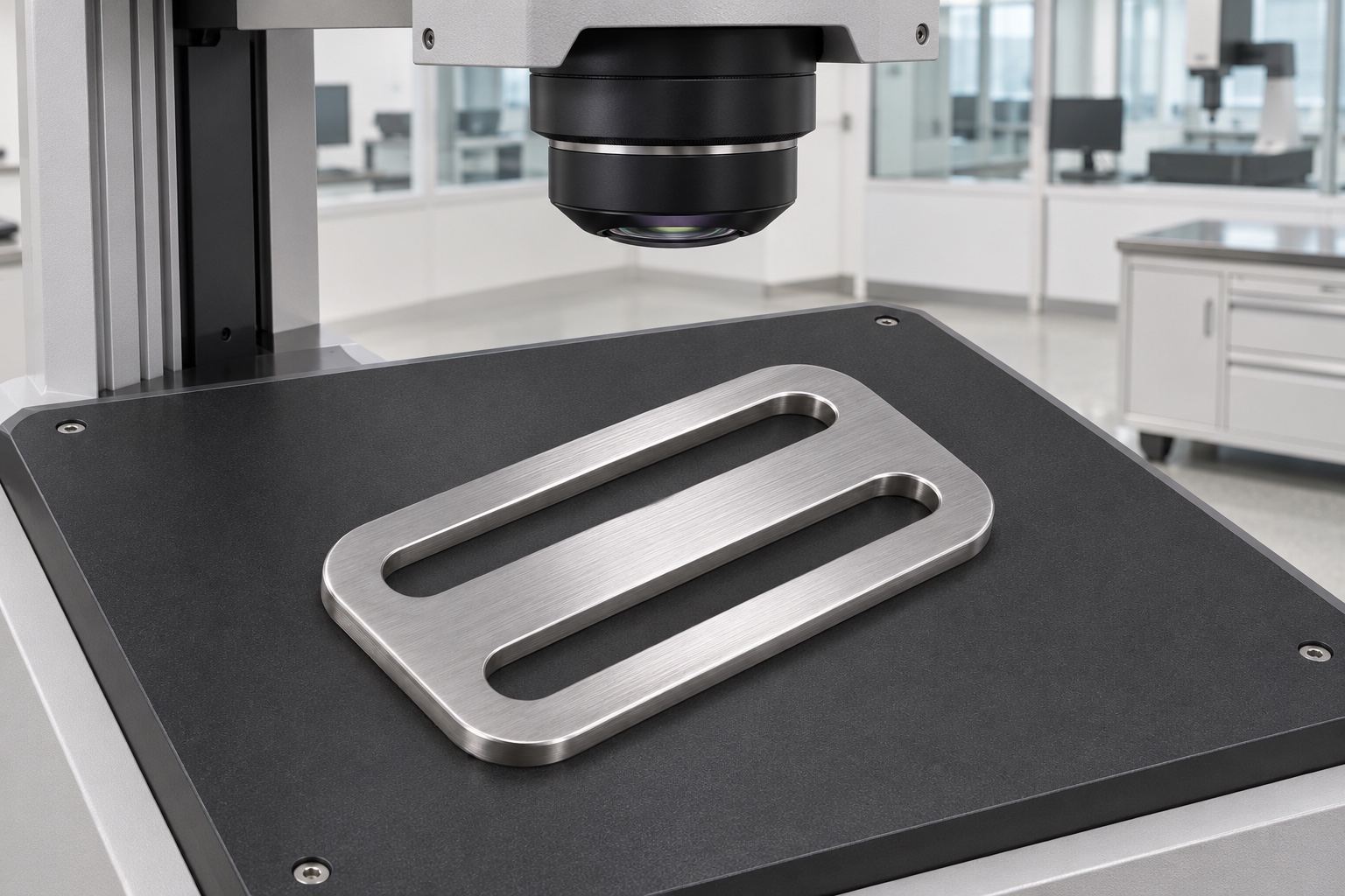
Map slot width, length, end shape, center spacing and position to suitable measurement methods. Optical or contact methods may be considered according to the actual feature size, access and required uncertainty. Explain the alignment used and how the free component is supported. A single overall caliper reading cannot automatically establish every aspect of a twin-slot pattern. Keep visual edge checks separate from dimensional results and identify any limited-access areas. The first-article report should contain genuine readings from a real component; a planning example does not establish capability, yield or achieved accuracy. Review the evidence before repeating the route across a low volume stainless steel order.
Use an inert mating reference for a bounded fit check
A defined dummy attachment element can supplement dimensional inspection by showing insertion access and visible interference. Identify its revision and the approved observation procedure. Do not force an uncertain clip through a slot or use an unusually flexible reference to hide a contour discrepancy. The check does not demonstrate patient-worn retention, drop resistance or long-term service behavior. If the drawing and the dummy disagree, investigate the definition before changing the metal. The useful question is whether the specific inert fixture interfaces assemble as intended, not whether a plausible-looking anchor plate can be presented as a validated accessory for every Holter recorder.
Keep cleaning and packaging requirements explicit
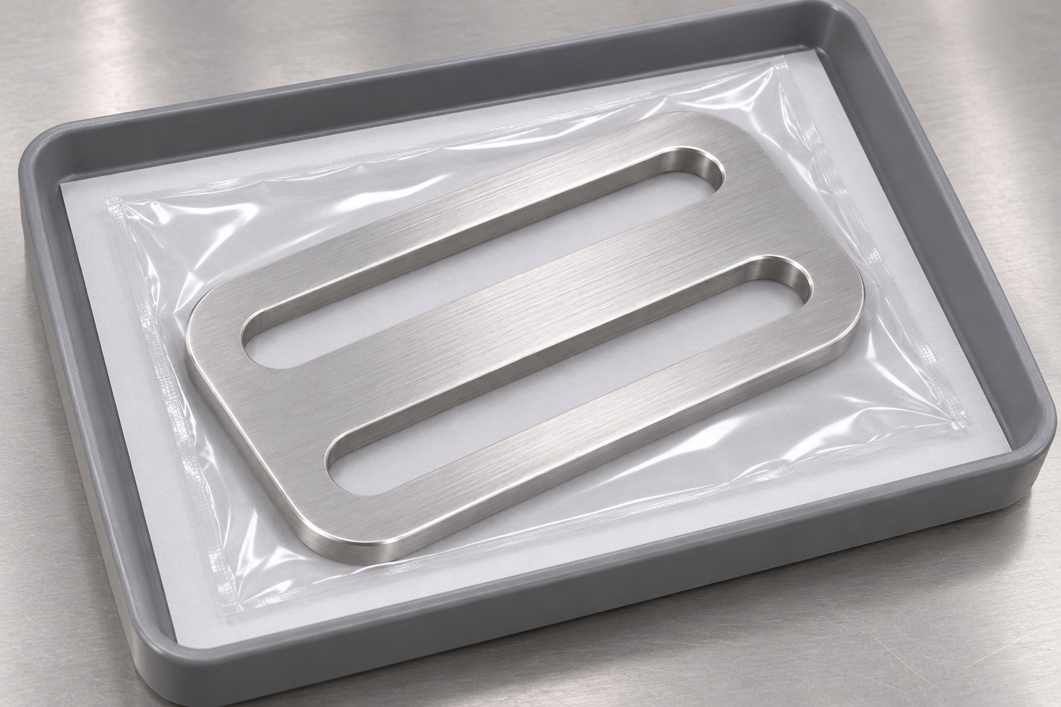
Define permitted cleaning agents, drying and handling before final packaging. Removal of loose machining debris does not establish sterility or an agreed quantitative residue limit. Keep slot interiors and the thin web away from abrasive packing material. Individual protective containment can prevent plates from rubbing together and mixing revisions. Place identifying information on the outer package unless direct part marking is approved. Any protective insert should not bend the plate or leave unacceptable debris. Receiving inspection still follows the actual purchase specification, and a clean-looking bag should not be treated as proof of medical-device suitability or a validated sterile barrier.
Prepare an RFQ for custom twin-slot CNC plates
Provide the released drawing and matching model, 316L designation, quantity and intended inert fixture use. Identify the approved slot contour, pattern references, thickness, edge condition and inspection deliverables. Include the defined mating reference if a supplementary bench check is requested. Ask the supplier to flag tool-access limitations or proposed substitutions before accepting the work. Preserve the approved setup and inspection decisions for repeat orders. A useful custom medical fixture parts quotation describes measurable manufacturing responsibilities and a clear acceptance process. It does not convert a drawing-based metal plate into a clinically approved attachment merely because the application name contains a medical recorder.
FAQ
Is this an approved wearable Holter accessory?
No. The guide addresses an inert fixture interface. Patient-worn use, device compatibility and retention performance require independent requirements, evidence and design-owner approval.
Which features define the twin-slot pattern?
Width, total length, straight segments, rounded ends, center spacing and position relative to the approved references must be specified. Slot count alone is insufficient.
Can a passing gauge verify the complete opening?
Not automatically. A gauge may check a defined local condition while missing the end contour, pattern position or geometric relationships required by the drawing.
Why measure after releasing machining clamps?
Restraint may conceal the plate's actual form. The inspection plan must evaluate the part in the state and support condition specified for acceptance.
Can deburring change the slot dimensions?
It should not alter the approved functional contour. Define edge treatment and inspect both sides so manual cleanup does not silently enlarge openings or thin the web.
What documents support a repeat order?
Retain the drawing and model revision, material identity, approved setup, actual first-article evidence, cleaning instructions and protective packaging requirements with the order record.

tanghangyun@oemach.com