
Identify the structural backing plate and its limits
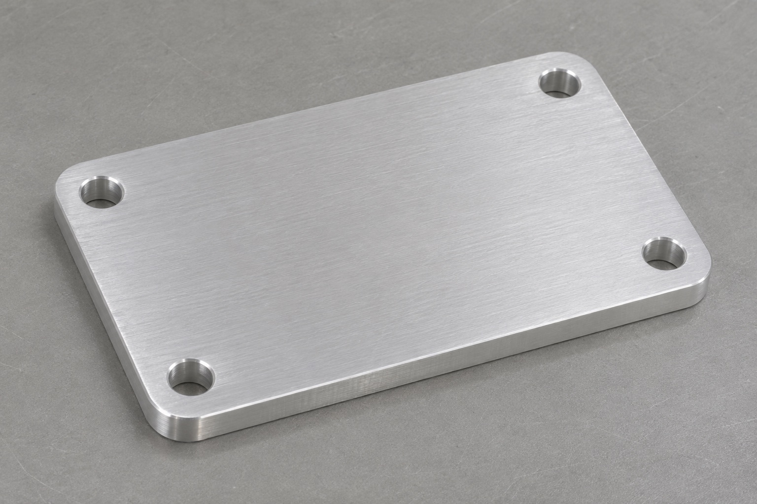
A forehead-rest backing plate is a structural interface behind another assembly, not automatically the patient-contact surface itself. This guide considers a simple 6061 aluminum plate for an unpowered fundus camera service fixture: a flat rectangular outline with rounded corners and four mounting through-holes. The example does not prescribe a replacement for a clinical instrument or establish any patient-contact suitability. Define the actual mating components and fixture purpose before deciding which dimensions need close control. Precision CNC milling is most useful when it preserves those relationships, rather than when every dimension receives the same unnecessarily restrictive tolerance without regard to the assembly.

Separate the mounting face from cosmetic surfaces
Mark the face that seats against the fixture and identify which opposite surfaces require protection during handling. A cosmetic finish and a geometric requirement solve different problems. The drawing should state the required seating condition and any surface texture requirement explicitly rather than relying on the word smooth. If a pad or other contact element sits above the backing plate, define its attachment independently. Do not infer pad compatibility, cleaning resistance or patient safety from the aluminum grade. This separation helps a custom ophthalmic equipment fixture parts supplier understand what can be inspected at the machine shop and what remains an assembly-level responsibility.
Specify the aluminum designation and supply condition
The order should identify the intended 6061 designation and temper, along with any required material records. A model file named aluminum plate is not a complete material specification. Confirm the stock form and the amount of material to be removed before choosing a blank. Keep the material identity associated with the traveler through cutting and machining. Any proposed substitution needs written review before manufacture. For a low volume CNC aluminum parts order, these decisions may be more important than a small difference in cycle time because an undocumented change can alter the assumptions behind finishing, dimensional evaluation or the receiving inspection plan.
Use a datum system that reflects assembly seating
Choose the seating face as a primary datum when that matches the assembly's function, then establish orientation and position from defined secondary references. Locate the four-hole pattern within that system. Avoid dimensioning each hole from a different rough edge or treating the outside profile as a substitute for the actual mounting relationship. The drawing should distinguish hole size from pattern location and orientation. Consider how the inspection setup will recover the same references without bending the plate. If the assembly uses clearance holes rather than locating pins, make that function clear so the supplier does not invent an unnecessarily tight fit requirement.
Review thickness and material removal before finishing
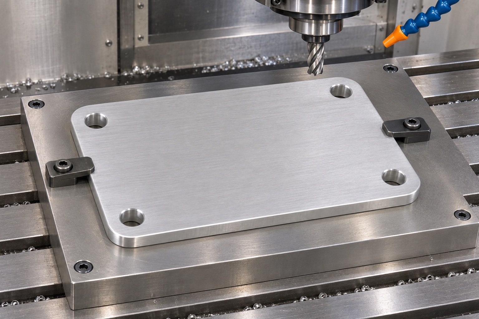
A flat stock blank does not guarantee that the finished plate will meet its specified condition after material removal and unclamping. Plan roughing, support and finishing around the actual geometry and stock condition. Where both faces require machining, review the order of operations and the material left for the final passes. A process plan may include a stabilization interval or another agreed intermediate step, but the choice must be justified for the job rather than assumed from a generic recipe. Measure the part in the defined state after release from workholding, because a compliant plate can appear different while restrained on a machine table.
Support the plate without hiding the finished condition
Workholding should prevent movement while leaving access to the required cutting paths. Use suitable support beneath broad surfaces and avoid concentrating clamp force near an unsupported thin edge. Document the support arrangement so a repeat batch does not depend on an operator recreating it from memory. A vacuum fixture, soft jaws or mechanical clamps may each be appropriate in different circumstances; none is automatically the correct answer for every plate. Review possible tool collisions and access to mounting holes before cutting. The inspection plan should also explain how the plate is supported when its final geometric condition is measured outside the machining fixture.
Machine the four-hole pattern with edge access in mind
The representative geometry uses four circular through-holes near the corners and no hidden channels or slots. Select drilling and finishing operations to meet the specified hole size and edge condition. Confirm that tools can exit into a clear space or approved support arrangement without damaging the fixture. Remove and inspect exit burrs without enlarging the holes by uncontrolled blending. If the real design needs threads or counterbores, show those features explicitly rather than assuming them from a screw model. The four holes should remain identifiable in the report so a positional discrepancy cannot be concealed by averaging unrelated measurements across the pattern.
Define corner and perimeter finishing deliberately
Rounded outside corners can make handling less awkward, but they are still controlled features. Specify the intended corner radius and edge condition according to the actual assembly clearance. Do not expand a corner radius during polishing to remove a cosmetic mark if that changes the mating outline. Keep seating faces protected while the perimeter is finished. Inspect the transition between the face and outside edge, including the areas near mounting holes. A consistent machined appearance is useful for review, but a photograph cannot demonstrate that the specified dimensions or geometric relationships are met. Use images to communicate the component, not to replace its inspection evidence.
Treat anodizing as a separate approved process
If anodizing or another finish is required, specify its type, appearance requirements, masking and inspection sequence with the responsible parties. Do not assume that a coating is harmless to every hole or mounting interface. The design owner should decide how treated surfaces are accounted for in the finished dimensions and which faces must remain untreated. A bare machined plate is also possible when the approved drawing calls for it. Neither option establishes compatibility with a particular cleaning agent or patient-contact application by itself. Keep manufacturing finish decisions separate from unverified claims about corrosion life, biological safety or medical certification.
Inspect the free component and record the setup
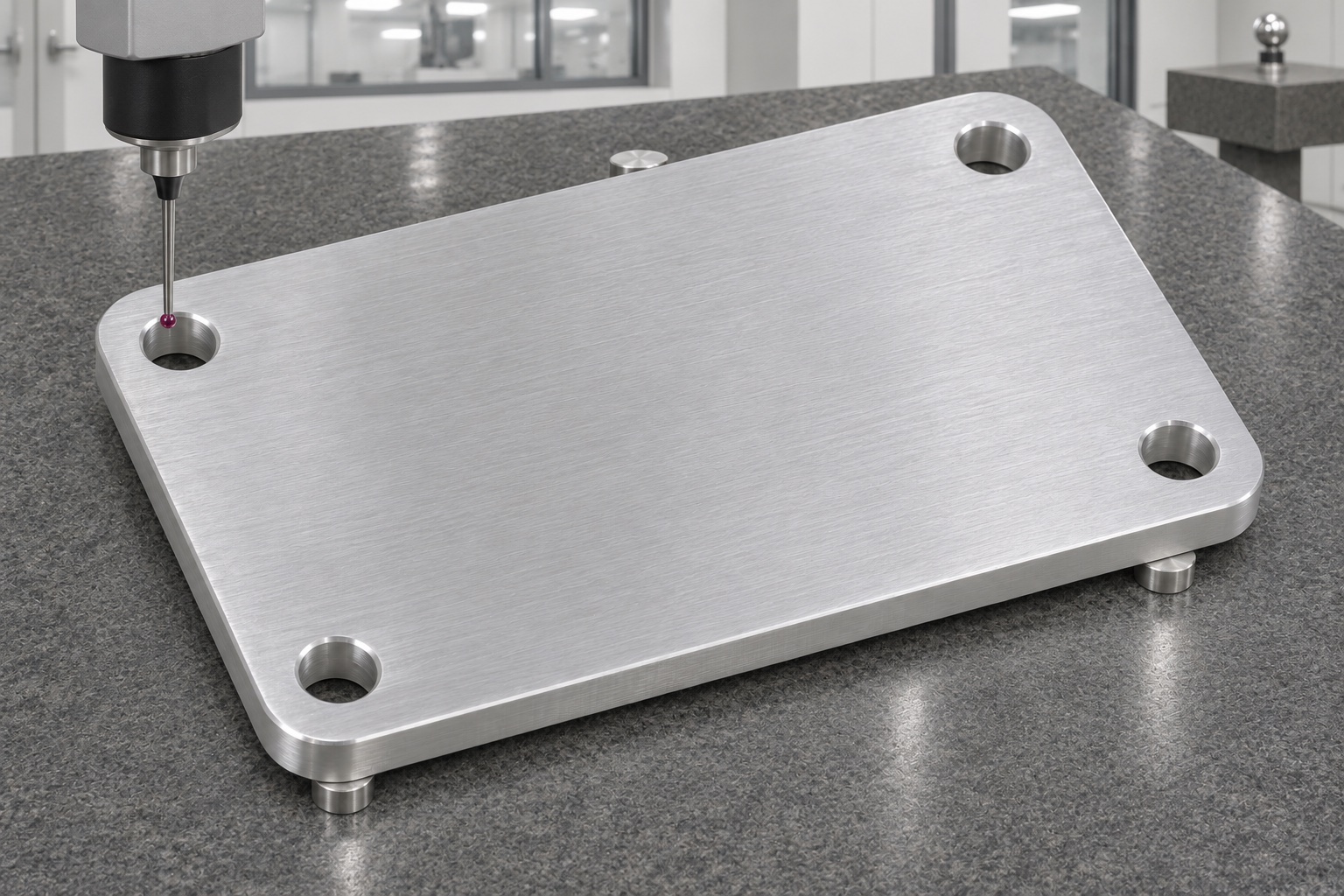
The first-article plan should cover thickness, the defined seating-face condition, outside profile and the mounting-hole relationships. State the support and reference alignment used for measurements, especially where clamping could influence the result. Use suitable methods for each requirement rather than assuming that one instrument verifies everything. Record actual readings and identify any limits of access or resolution. A bench assembly check can supplement the report, but a plate that can be bolted down is not necessarily geometrically conforming when free. For repeat CNC milling orders, preserve the approved inspection setup so changes in the measurement method do not masquerade as changes in the part.
Protect aluminum faces through cleaning and packaging
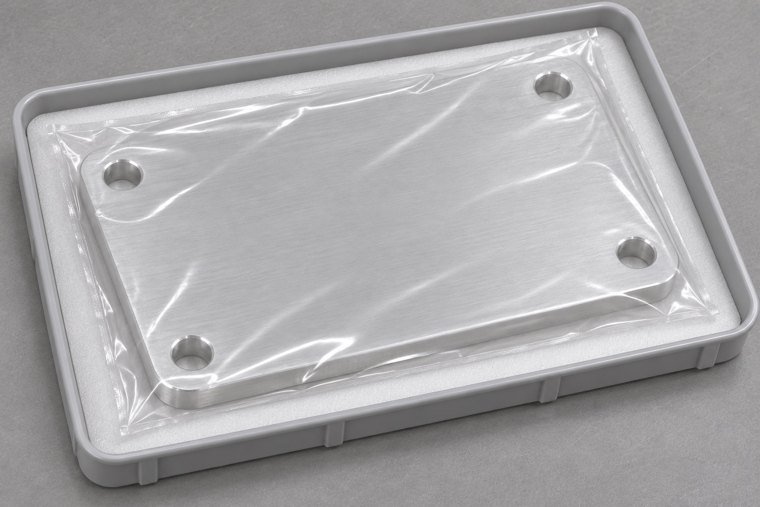
Agree the cleaning method, drying procedure and packaging materials before final inspection or shipment. Keep abrasive debris away from the seating face and avoid rubbing several plates together in a shared bag. Individual separation can protect the machined surfaces and keep part identity visible. Labels should state the part and revision without adding unsupported sterile or medical-grade claims. If a protective film is proposed, confirm that its adhesive and removal process are acceptable for the order. Clean-looking packaging is not a validated sterile barrier, and receiving inspection should still follow the actual purchase specification and any handling restrictions set by the buyer.
Write an RFQ around measurable fixture interfaces
Provide the plate drawing, a matching model, 6061 designation and temper, quantity and the intended unpowered fixture use. Identify the mounting pattern, seating face, thickness requirements and any approved surface treatment. Request a first-article report that uses the same datum definitions as the drawing. Ask for clarification on workholding, coating allowances or inspection access before authorizing production. This supports a practical custom aluminum CNC machining quotation without converting the plate into a clinical performance claim. The strongest purchasing description explains what must fit, how that condition will be evaluated and which responsibilities remain with the assembly's design owner.
FAQ
Is the backing plate the patient-contact pad?
Not in this example. It is a structural plate for an unpowered service fixture. Patient-contact elements and their suitability require separate specifications and review.
What material information belongs in the RFQ?
Provide the intended 6061 designation and temper, stock or documentation requirements, drawing revision, quantity and any approved finish or substitution restrictions.
Why inspect after removing machining clamps?
Restraint can influence the measured plate condition. The inspection plan should define support and evaluate the component in the state required by the drawing.
Are four holes enough to define the mounting interface?
The hole diameters, their pattern and relationship to the seating references must all be specified. Hole count alone does not define an acceptable interface.
Is anodizing included automatically?
No. Its requirements, masking, dimensional treatment and inspection sequence must be approved separately. A bare machined finish may be specified instead.
Can assembly fit replace the first-article report?
No. A supplementary fixture check does not automatically verify free-state geometry or every drawing requirement. Actual dimensional evidence remains necessary where specified.

tanghangyun@oemach.com