
Define the pivot block before selecting a machining route
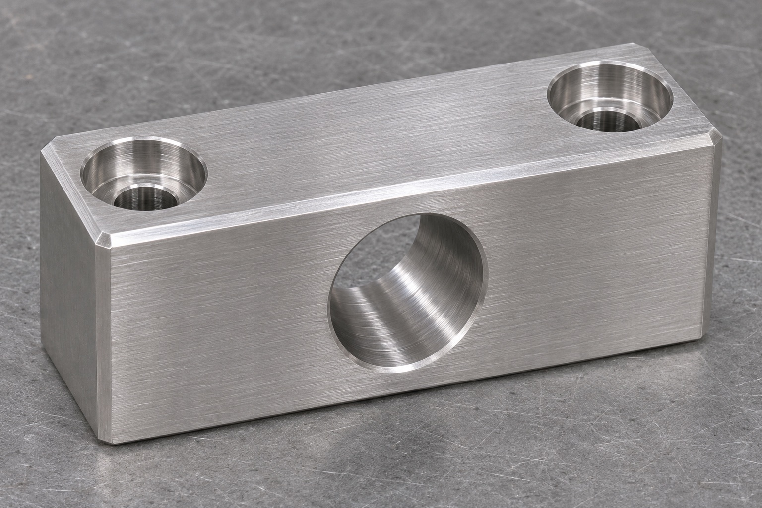
A latch pivot block connects a pin axis to a mounting interface. For a surgical smoke evacuator service fixture, that relationship deserves more attention than the external rectangular outline. This guide considers a compact 316L stainless steel block with a transverse bore and two vertical mounting holes. The example is intended for an unpowered bench fixture, not a released replacement for an operating device. A drawing must identify the actual mating pin, mounting surface and inspection requirements. Precision CNC machining starts with those interfaces, because an attractive block can still locate the pivot incorrectly when the wrong face becomes the manufacturing reference.

Separate fixture requirements from medical device approval
The application name does not establish clinical suitability. A drawing-based CNC machining service can manufacture a defined geometry, but the device owner remains responsible for approving any use in working equipment. Record whether the block belongs to a training fixture, a maintenance simulator or a development assembly. Keep fluid pathways, filtration performance and powered operation outside this example. If the intended use later changes, reopen the specification rather than carrying forward assumptions from a bench part. This boundary also improves purchasing: the supplier can quote documented manufacturing work without inventing certification, contamination limits or service-life promises that the order never established.
Specify 316L stock and preserve material identity
Use a written material designation and the required supply condition, rather than accepting a generic stainless description. The purchase order should state which material documents are required and how their identity follows the cut blank into the job traveler. Label containers or travelers instead of marking a functional bore without permission. Confirm any substitution before cutting, including a different stainless grade or an alternative product form. For low volume stainless steel machining, a small quantity is not a reason to lose traceability. Material documentation supports identity; it does not by itself prove that a finished component is suitable for a particular medical device.
Establish mounting and bore datums together
Choose a stable mounting face as the primary reference and a long side as a secondary orientation reference when the drawing supports that scheme. Locate the transverse bore relative to those references, not merely relative to whichever blank edge happens to be easiest to probe. Distinguish the bore diameter requirement from its position and direction. Two holes can have acceptable diameters while their relationship prevents the pin from seating as intended. Make the drawing and inspection plan describe the same coordinate system. If a fixture pin is used during inspection, explain which freedom it constrains and avoid forcing the part into an apparently favorable reading.
Review the mounting holes for machining access
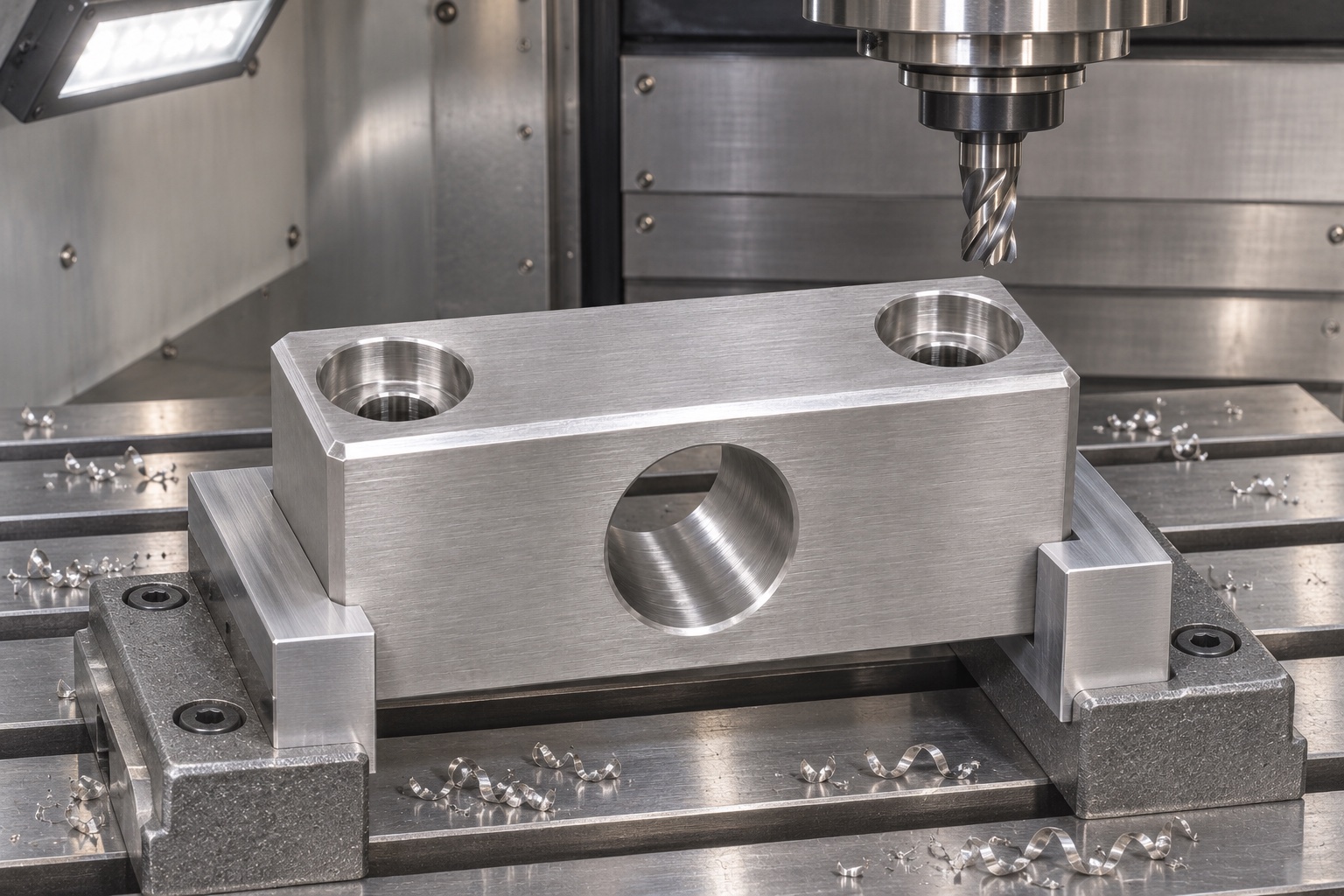
Place the vertical mounting holes so their paths do not accidentally intersect the transverse bore. If an intersection is intentional, the drawing must show it and define how the resulting internal edges will be inspected and finished. Counterbore depth, screw-head clearance and remaining wall thickness all need explicit review. Do not add a deeper recess simply because a preferred screw does not sit flush in an early model. The screw and the block must be evaluated as an assembly. A clear section view often resolves more uncertainty than several additional decimal places on the external width, especially when access is limited after installation.
Plan rough milling around reliable support
Prepare the block with sufficient stock for finishing the reference faces after rough material removal. Use positive support beneath the workpiece and a clamping arrangement that leaves the tool path clear. A first operation should create useful references for the subsequent bore operation, rather than finishing an arbitrary decorative face first. Review the setup in CAM and at the machine before cutting. The appropriate cutting parameters depend on the actual tool, stock, coolant and machine condition; they are not supplied by the component name. Record the approved setup so a later small batch does not quietly start from a different reference strategy.
Finish the transverse bore as a functional feature
The choice between drilling, boring and reaming follows the specified bore condition and available access. A drilled pilot may establish a path, but the final process must address the required size, geometry and surface condition together. Keep the bore supported and ensure that the tool can enter and leave without striking fixtures. Do not treat a pin that can be pushed through as a complete dimensional inspection. A pin may reveal a gross obstruction but cannot automatically establish bore position or direction. Where separate operations are necessary, document how the second setup recovers the mounting reference without relying on an unfinished edge.
Control chamfers without changing the load-bearing interface
Separate entry chamfers, handling edges and functional bearing surfaces on the drawing. A generous hand-blended edge may feel smooth while removing material that the pin or screw head was intended to contact. Define an appropriate edge condition and select tools that can reach it consistently. Inspect both bore entrances and the underside exits of the mounting holes. Remove loose chips before judging the result, since a trapped fragment can resemble a damaged edge. If an internal edge cannot be viewed or reached, resolve that limitation during process planning instead of accepting an unverifiable deburring step at the end of production.
Build an inspection plan that measures relationships
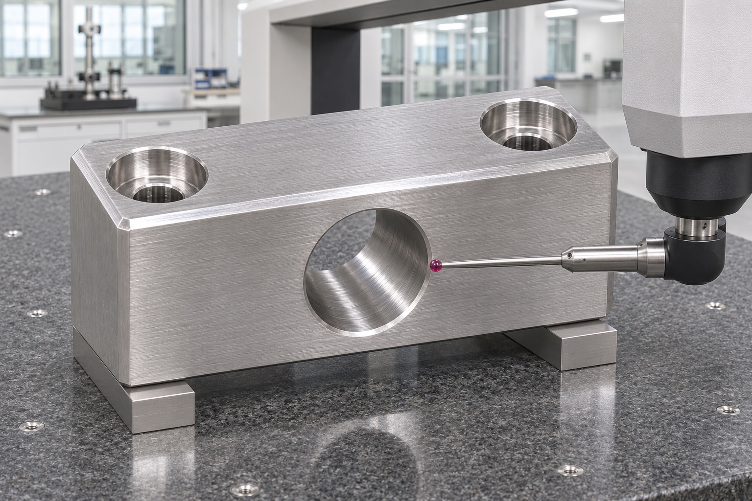
Map every critical drawing requirement to a suitable inspection method. Bore size, mounting face condition, hole spacing and bore-to-face position are different tasks and may require different equipment. A coordinate measuring setup should use accessible probing paths and a documented alignment. Record the instrument, method and any inspection limitations in the report. Do not claim a capability value from a single representative part or replace an actual measurement with a nominal CAD dimension. The first-article review should establish that the proposed manufacturing route can be evaluated credibly before the same route is repeated across a low volume CNC order.
Define cleaning as a documented manufacturing step
Specify the permitted cleaning agents, drying method and handling precautions for the order. A visually bright stainless block is not evidence of an agreed residue condition, and ordinary cleaning is not a claim of sterility. If the buyer requires a particular cleanliness assessment, define its method and acceptance criteria separately. Keep the bore free from loose machining chips before protective packaging, and avoid pushing contaminated cloth through a finished interface. Any additional surface treatment needs its own approval and inspection sequence. The objective is a documented, reviewable condition at shipment rather than an unsupported description such as medically clean.
Protect the bore and reference faces during shipment
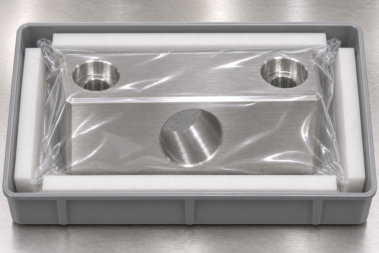
Use individual protective packaging that prevents metal-to-metal rubbing and keeps loose packing material away from the bore. Identify the part and revision on the outer package or traveler, leaving the component unmarked unless marking is authorized. A protective cap or insert must not shed material or distort a thin feature, and its use should be agreed in advance. Keep inspection records connected to the packaged lot. Packaging protects the inspected manufacturing condition; it does not convert a bench fixture component into a sterile device component. Reinspection after unpacking may still be necessary when the receiving procedure calls for it.
Prepare a complete request for custom CNC machining
A useful RFQ includes the released drawing, a matching model, material designation, quantity, intended fixture use and a list of inspection deliverables. Identify the bore and mounting interfaces that control fit, along with the approved edge condition and cleaning instructions. Ask the supplier to disclose inaccessible inspection areas or proposed substitutions before manufacture. For repeat orders, retain the drawing revision, setup references and first-article decisions as one package. This makes custom medical equipment fixture parts easier to purchase without substituting vague promises for measurable requirements. Release the order only after the manufacturing and inspection responsibilities are understood by both parties.
FAQ
Is this block an approved smoke evacuator spare?
No. The guide concerns an unpowered service-fixture example. Use in operating equipment requires separate design-owner review, documented requirements and applicable approval.
Which dimensions matter beyond bore diameter?
The bore location and direction relative to the mounting references, mounting-hole pattern and specified edge conditions also affect the defined assembly interface.
Can mounting holes cross the pivot bore?
Only when the drawing intentionally permits the intersection and defines accessible internal-edge finishing and inspection. Do not introduce an intersection as an undocumented machining shortcut.
Does a passing pin replace dimensional inspection?
No. It can detect certain obstructions or fit problems but does not automatically verify the bore's position, direction or complete geometric requirements.
Does ordinary cleaning make the block sterile?
No. Cleaning, residue assessment and sterilization are separate requirements. Only claim processes and acceptance criteria that were specified, performed and documented.
What information is needed for a quotation?
Provide the drawing and model revision, 316L designation, quantity, fixture purpose, critical interfaces, inspection deliverables, cleaning instructions and protective packaging requirements.

tanghangyun@oemach.com