
Define staging rather than sealing or processing
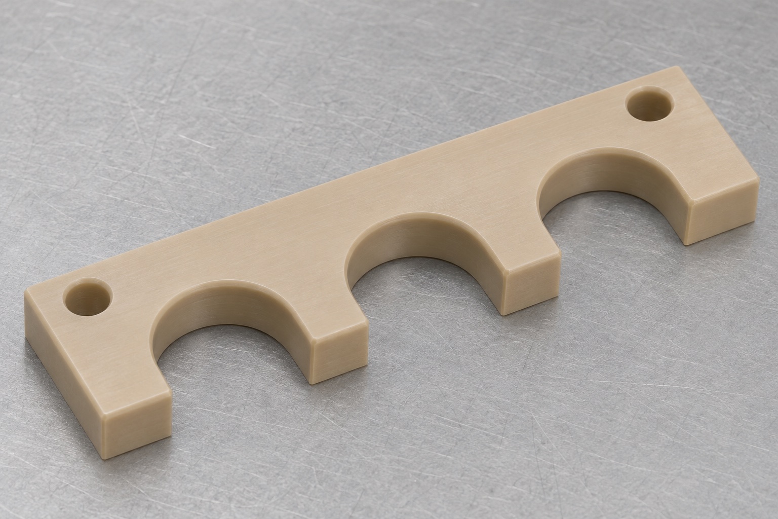
A cap staging comb can organize identified inert cap references while a laboratory fixture is developed. The representative PEEK component here is an elongated flat bar with three identical U-shaped open slots along one long edge and two plain mounting holes in the uncut rear strip. It is not a closure, a sealing tool or an automated processing system. Precision CNC milling begins by defining the slot contacts, center spacing and mounting references. This guide is limited to a non-operating bench setup. It does not establish specimen protection, cryogenic performance, sterility, cap torque or compatibility with a validated laboratory workflow.

Obtain the controlled cap envelope
Ask for the cap geometry that actually contacts the comb, including its maximum relevant envelope, edge shape and approved insertion direction. A nominal outside diameter may omit a skirt, rib or projection. State whether the cap rests against the slot root or is located by another feature in the fixture. An inert sample should have an identified revision and condition rather than represent an unspecified family of caps. The designer must set clearance and support requirements. Do not assign a slot radius from one convenient sample and then claim that every cryovial cap will stage correctly in the resulting comb.
Relate all three slots to common datums
Define slot centers, profiles and orientation from the same approved reference system. A rear edge and support face may establish the relevant position if that matches the assembly. Equal nominal spacing does not prove that the three slots are correctly located relative to the mounting holes. Inspect their pattern as well as each local opening. The drawing should identify which surfaces contact and which only provide clearance. A comb that accepts a sample in each slot can still have incorrect pitch or a shifted pattern. Such errors matter to the mechanical fixture even though a casual manual check may not reveal them.
Specify the actual PEEK grade and stock
Identify the approved polymer grade, filler condition, stock form and procurement documentation. This representative part uses natural unfilled PEEK, not an unidentified tan plastic or a reinforced substitute. Preserve material identity through blank preparation and avoid mixing remnants without traceability. The name cryovial does not make this a cryogenic application specification. If temperature exposure, reagents or cleaning conditions are relevant to a real order, define them separately and assess the exact grade against those requirements. No medical certification, biocompatibility, sterility or chemical compatibility follows automatically from selecting PEEK for a machined bench fixture component.
Support the rear strip while roughing slots
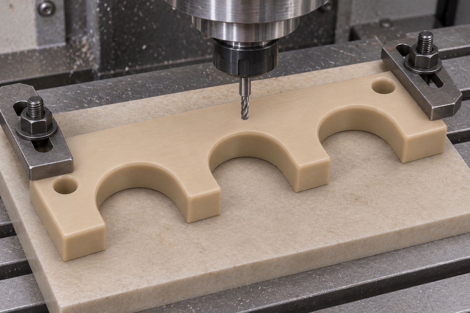
Prepare reference surfaces while the blank has enough stiffness. Rough the three open slots with allowance for finishing, preserving the rear strip and the material between openings. Workholding should avoid bending the bar or squeezing the emerging prongs into an artificial pattern. A sacrificial support can permit through cutting where appropriate, but chip trapping beneath the part must be controlled. Review tool diameter and access against the slot roots. Choose cutting conditions for the actual grade, tool and machine rather than copying universal values. Verify the proposed sequence by measuring physical parts after release and appropriate conditioning.
Finish roots and entry regions deliberately
An open U-profile contains an entry region and a curved root that may have different contact roles. Define their geometry clearly, including any permitted lead-in or edge break. A cutter path that achieves a nominal radius can still leave a local ridge at the transition to a straight wall. Inspect these transitions rather than assuming a smooth-looking slot has the correct profile. Do not hand-sand every opening until an uncontrolled cap feels comfortable. That can change local clearance and center location without producing traceable conformance. Any alteration to the intended contact region should follow approved rework or a controlled design change.
Keep the rear mounting holes plain
The representative comb has two plain through holes in its uncut rear strip. Their axes are normal to the broad support face. They are not threaded, countersunk or intended to pierce the open slot regions. Confirm hole size, location and the specified fastener arrangement before programming. A bolt pattern should not pull a bowed comb flat unless the drawing explicitly defines a restrained acceptance condition. Inspect both exits for burrs and maintain enough material around the holes according to the design. If a different retention method is required, revise the interface rather than adding extra holes or screw seats informally.
Deburr without thinning the prongs
Inspect slot mouths, curved roots, prong tips and mounting-hole exits for loose plastic strands. Remove burrs without uncontrolled rounding, smearing or material loss at the contact profiles. Thin projecting regions can be damaged during aggressive hand finishing even when the main bar remains intact. Use appropriate lighting and magnification. Protect the support face from embedded debris that could affect later measurements. Cleaning should remove process residue to the agreed condition, not be described as sterilization or validated laboratory decontamination. If a quantified cleanliness requirement applies, its method and acceptance evidence need to be specified separately from ordinary protective preparation.
Condition and inspect the released pattern
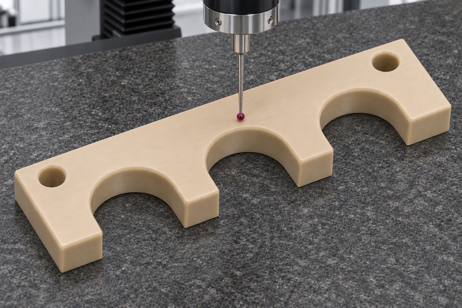
Allow the plastic component to reach the agreed measurement environment before acceptance. Temperature, support and contact force can influence the observed geometry. Measure each slot profile and the center pattern from the approved datums, with appropriate checks on support-face form and mounting holes. Low-force or noncontact methods may be useful where probe loading would move a prong. A single width measurement across a slot mouth does not establish the root profile or position. The report should identify the reference alignment, support condition, instrument and actual results, making comparison with the buyer's later incoming inspection meaningful.
Use identified inert caps for a limited trial
An unloaded bench trial can place identified inert cap references into each slot using the approved direction. Record revisions, mounting condition and points of first contact. Observe insertion and removal without applying an operational capping process, using specimens or claiming a sterile workflow. A smooth trial does not establish sealing, closure torque, cryogenic suitability or automated handling reliability. If one slot binds, inspect its local profile and the cap reference before widening the entire pattern. If all positions change after mounting, review the support surface and fastener arrangement. Mechanical observations should remain separate from complete laboratory-process qualification.
Diagnose pitch and profile errors separately
If each cap fits locally but the fixture pattern does not align, inspect slot center spacing and mounting references. If contact occurs only at a root transition, inspect the local profile and cap edge geometry. If a prong moves under measurement, review support and measurement force before concluding that a machining offset is wrong. Document the first interference and related dimensional evidence. A correction should address the confirmed cause, with approval and reinspection of affected features. Enlarging every slot may conceal a pattern error while reducing intended support. Preserve traceable records so a repeat batch does not depend on undocumented manual adjustments.
Quote the complete staging fixture component
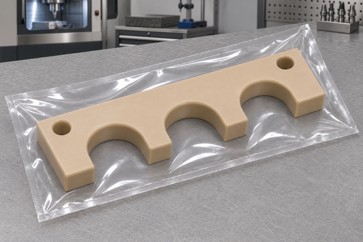
Supply matching drawing and CAD revisions, PEEK grade, quantity, cap envelopes, mounting hardware requirements, final surface condition and inspection deliverables. State who supplies inert references and whether a dedicated pattern fixture is included. Separate first-article reporting and special tooling from the repeat-part price where appropriate. Protective packing should support the bar and leave the prongs free from bending loads or loose hardware. Maintain revision and material identity with the release records. This defines a verifiable custom laboratory fixture scope while leaving specimen handling, sealing, temperature exposure and complete workflow qualification with the responsible laboratory or equipment organization.
FAQ
Is the comb a cryovial sealing tool?
No. It is a representative staging fixture component. It does not define sealing, closure torque, specimen protection or an operating capping method.
Does the word cryovial establish low-temperature suitability?
No. Actual temperature exposure must be specified and assessed separately for the exact material and geometry. This example describes an inert bench setup.
Why inspect the three-slot pattern as well as individual slots?
Local cap fit does not establish center spacing or location relative to mounting features. The drawing may require both profile and pattern inspection.
Can the rear holes be countersunk by default?
No. This example has two plain through holes. Different screw seats, threads or retention methods require approval before machining.
Why use low-force or noncontact inspection?
Measurement loading can move a slender prong. Select a method suited to the geometry and record the support and acceptance condition.
Does a successful manual staging trial validate laboratory use?
No. It only records mechanical fit with identified inert references. Sterility, specimens, sealing and automated workflow performance require separate qualification and evidence.

tanghangyun@oemach.com