
Define the carrier as a mechanical support
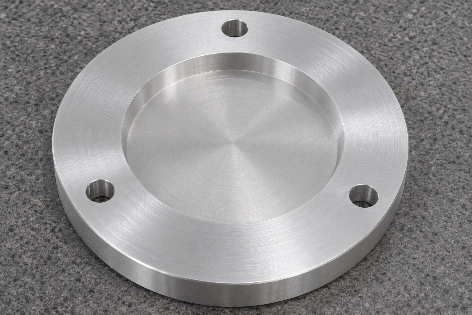
An optical coherence tomography service fixture may require a separate carrier for an identified target reference. The representative component here is a flat circular 6061 aluminum disc with one shallow blind central pocket and three plain axial mounting holes around its outer flange. It is a mechanical support, not the target itself or a calibrated optical reference. Precision CNC machining should distinguish the pocket's seating function from the flange's attachment function. This guide covers a non-operating bench assembly with an inert target envelope. It does not establish optical alignment, calibration accuracy, image quality or compatibility with a particular clinical OCT instrument.

Request the target envelope and installation direction
A nominal target diameter alone does not describe how a target enters and seats. Ask for the controlled outer envelope, thickness, edge radius, orientation and any required removal clearance. Identify whether the pocket floor supports the target or a separate insert provides the final contact. A blind pocket must not be confused with a through aperture. Confirm that the target can be removed without prying against a functional surface. The carrier designer should define these interfaces explicitly. A machining supplier cannot infer optical spacing or acceptable target position from a photograph, a generic instrument name or an uncontrolled sample.
Set the flange and pocket datum relationship
The rear flange face may provide the primary support plane when it seats on a fixture. Define how the circular body is centered and how angular orientation is established. Three equally spaced mounting holes do not necessarily provide unique clocking, so mark or constrain orientation only when the approved design requires it. Specify pocket depth and floor orientation from the relevant support face rather than from an arbitrary stock surface. A correctly sized recess can still place the target at the wrong height if the disc thickness or supporting plane is wrong. Inspection references should reproduce the intended mechanical relationship.
Choose 6061 stock and the accepted finish
State the alloy, temper, product form and any documentation needed for the actual order. Maintain material identity through blank preparation. Select enough thickness allowance to establish the back support face and the pocket without forcing a distorted blank flat. The order should identify whether the disc is supplied bare or with a specified treatment. Appearance does not establish optical performance, electrical isolation or compatibility with cleaning chemicals. If coating is required, define its effect on the pocket, mounting face and holes before cutting. Unspecified finishing after acceptance can change the mechanical relationship that the supplier originally measured and documented.

Turn the circular references where appropriate
CNC turning can establish the circular outside profile and reference faces efficiently when the stock and workholding permit it. The central blind pocket may also be turned or later milled depending on the drawing, machine and access. Choose the process for controllable geometry rather than assuming every round part needs a single setup. Document how a second setup recovers the established reference system. Avoid gripping the finished flange so heavily that it bends during machining. The released disc, not its temporarily constrained shape in the chuck, must satisfy the agreed acceptance condition after it reaches the specified inspection environment.
Machine a genuinely blind pocket
The pocket has a solid floor with a defined remaining wall thickness. Program the depth from the approved reference and review tool access to the corner radius. An excessive local depth can reduce the remaining section even when the target still seems to fit. Consider the transition between floor and wall, since a target's edge radius must clear it to seat properly. Keep tool marks and local ridges within the specified surface requirements. Do not turn a nominally flat seat into a hand-polished hollow to improve appearance. Any change to the pocket's contact region needs an approved requirement and a measurable acceptance method.
Locate three plain axial mounting holes
The representative flange carries three small through holes equally spaced around the pocket. Define their pitch circle and angular relationship to the datum system where required. Confirm that they are plain clearance holes; countersinks, threads and dowel fits are different features. A three-hole pattern can appear symmetrical yet have an incorrect radius or an offset center. Inspect the pattern using the specified references rather than measuring each hole only from the outside edge. Support drill breakout and remove burrs from the rear face so the disc can seat without rocking. Do not use fastening force to pull an incompatible pattern into alignment.
Prevent edge finishing from changing seating
Remove loose material at the pocket entrance, flange rim and both ends of each mounting hole. Preserve the specified floor and wall geometry, especially where an edge break meets the target's seating envelope. A generous cosmetic chamfer can reduce useful support or change removal clearance. Inspect small corners with suitable lighting rather than judging the whole disc by its reflective finish. Clean the blind pocket so trapped chips do not become false seating points. Protective cleaning is not a validated device reprocessing method. If a more demanding cleanliness condition is needed, define its process and evidence before manufacturing rather than implying it from packaging appearance.
Measure depth and floor form separately
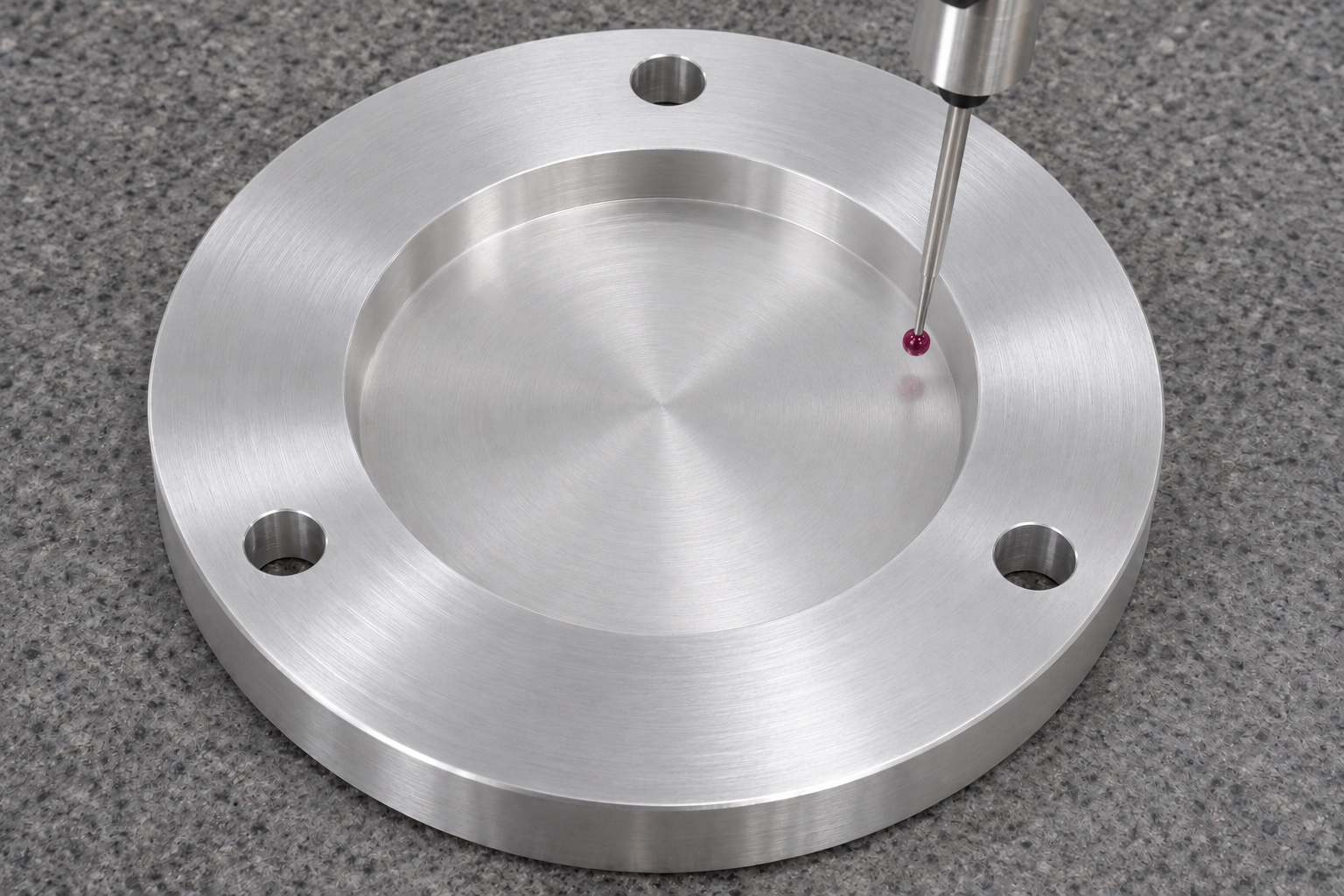
Use a suitable method to measure pocket depth from the specified plane and assess floor form across the intended contact region. A single depth reading cannot reveal a tilted or locally dished floor. Inspect outside diameter, disc thickness and mounting-hole pattern as separate drawing characteristics. Choose probe locations away from corner blends and specify the support condition. Where a coordinate measurement system is used, confirm access to the pocket floor without contact with the rim. Record the instrument, reference setup and actual results. A loose target coupon is a supplemental assembly reference, not a replacement for controlled dimensional inspection.
Review an unloaded inert target assembly
An identified inert target envelope can reveal interference at the pocket wall, root radius or mounting pattern. Use a non-operating service fixture and document the references, revisions and seating condition. Observe insertion and removal without using a live optical system to justify mechanical acceptance. A target that sits visibly flat does not prove calibration or imaging performance. If it rocks, inspect both the carrier floor and target reference before changing either. If fastening alters the fit, review the flange support, screw arrangement and mating fixture. The trial should isolate mechanical contact, not substitute for the equipment owner's optical qualification plan.
Control coating and revision changes
A later coating change can affect pocket diameter, depth and target seating even if the CAD model remains unchanged. A revised target may also have a different edge radius or thickness. Confirm both component and mating-reference revisions before repeating production. Preserve separate process checks before finishing and final acceptance checks afterward where the order requires both. Do not silently reuse a previous offset to compensate for a changed target sample. The drawing and approved deviation process govern the interface. Traceable decisions make custom medical optical fixture parts easier to reorder without suggesting that the supplier has calibrated or approved the complete instrument.
Quote the complete mechanical scope
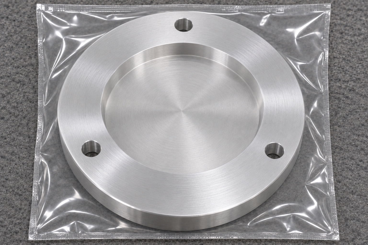
A useful RFQ contains controlled drawing and CAD files, material and temper, target envelope, mounting information, finish, quantity and inspection requirements. Specify who provides the inert target reference and whether fixture development or a first-article report is included. Identify surfaces requiring protection from scratches or packaging contact. Pack the disc so its flange stays supported and the blind pocket cannot collect loose hardware or debris. Keep revision and material identity linked to the inspection record. This provides a verifiable CNC machining scope while leaving the target's reference value, optical adjustment and instrument qualification with the responsible service or equipment organization.
FAQ
Is the carrier itself an OCT calibration target?
No. It is a mechanical support for a separately defined target. Its geometry does not establish calibration value, optical accuracy or image quality.
Does the central pocket go through the disc?
No. The representative design has a blind pocket with a solid floor. Remaining wall thickness must follow the approved drawing.
Why inspect pocket depth from the flange reference?
The supporting flange determines the installed relationship. Measuring from an unrelated stock surface can conceal an incorrect target seating height.
Do three equally spaced holes define one angular position?
Not necessarily. The designer must specify clocking or another orientation feature if the assembly requires a unique angular position.
Can a target fit replace floor-form inspection?
No. A fit observation supplements inspection but may not reveal local dish, tilt or geometry outside the target's actual contact region.
What changes require a new interface review?
Review target revision, material or finish changes, mounting alterations and changed acceptance conditions. Reconfirm how each affects seating, clearance and inspection references.

tanghangyun@oemach.com