
Separate a clamp half from a complete assembly
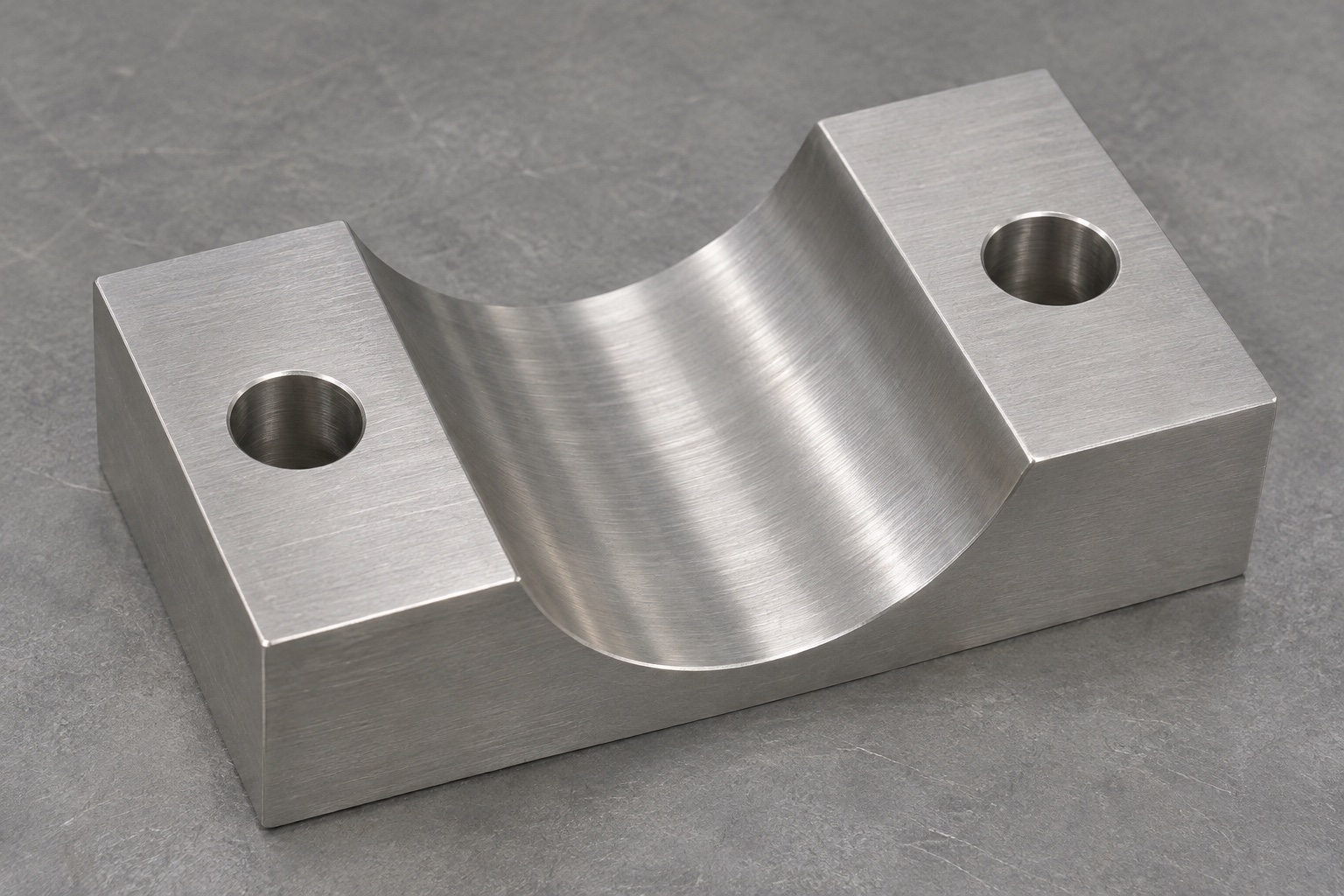
A pole saddle clamp half is only one mechanical component of an accessory mounting arrangement. The representative 316L part here has a rectangular body, an open semicylindrical groove across its upper face and two plain mounting holes, one on each flat ear. A mating half and fasteners would be defined separately. Precision CNC milling begins by identifying which surfaces seat, locate and fasten the assembly. This guide addresses an unloaded bench fixture using an inert pole reference, not an operating suction system. It does not assign holding force, safe working load, transport security or suitability for supporting medical equipment near a patient.

Define the pole envelope and contact intent
Request the approved pole diameter range, straightness information and surface condition relevant to the proposed mechanical interface. The groove may be intended to contact over a defined region rather than match a nominal cylinder everywhere. State how the mating half closes and whether a designed gap must remain between the ears. A loose cylinder sample cannot establish the allowable diameter range. Do not remove material from both halves until they touch if the drawing requires a gap. The designer must define the intended contact and retention system; the machining supplier should not invent torque settings or load limits to compensate for missing assembly information.
Relate groove position to the mounting ears
The groove axis and the ear surfaces define different geometric relationships. Establish a reference system that matches how the half is supported during inspection and assembly. A rear or lower face may establish the primary plane, with a defined edge completing lateral location. Specify the groove center height, orientation and profile from those references. The ear hole pattern should be located independently of the cosmetic perimeter where the assembly demands it. A correct radius alone does not prove correct seating. The groove can be shifted, tilted or locally distorted while a diameter gauge still seems to fit at one short section.
Select traceable 316L stock before programming
Identify the specified 316L grade, product form and supply condition, and keep the material lot associated with the work order. A supplier should not replace an unknown stainless offcut with a visually similar alloy. Provide enough machining allowance to establish stable mounting references without unnecessary stock removal. Review whether the rough shape will remain stiff after the groove is opened. Alloy identity does not establish cleaning compatibility, corrosion performance in a particular environment or device certification. Any additional documentation or surface treatment requirement belongs in the order. Resolve those requirements before quoting custom stainless steel clamp parts rather than adding assumptions after machining.
Rough the curved seat while support remains
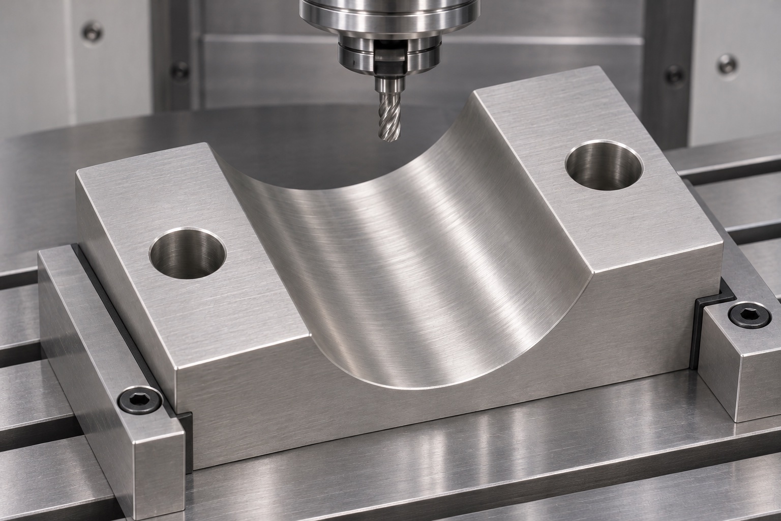
Establish the reference faces and rough the groove with a sequence that preserves support beneath the remaining section. Tool choice depends on the approved radius, groove length and access from the open ends. A ball end mill, form tool or another suitable process may be considered, but none should be selected solely because it resembles the final curve. Review cutting engagement, tool reach and chip clearance. Avoid rubbing with a worn edge or recutting trapped stainless chips. Leave a controlled finishing allowance and inspect the released condition before committing to the final pass, especially when the two ears are relatively thin.
Finish the cylindrical profile without hidden ridges
A scallop or local ridge can create first contact at an unintended place. Define the surface texture and profile requirement in the actual seating region, and select a finishing path that can be inspected. Tool-path spacing and cutter form influence the residual surface, but a visual shine does not prove form accuracy. Check the transition at each open end and the blending near the ears. Do not hand-polish the seat until a single pole sample appears comfortable. That approach can enlarge the groove locally and destroy its relationship to the drawing. Changes to contact geometry require approved disposition and a repeatable measurement method.
Keep the two mounting holes as plain holes
This representative half has two plain through holes, not threads, countersinks or counterbores. The mating assembly provides the specified fastener arrangement. Confirm hole diameter, center spacing and orientation from the approved references. A mounting ear should not be pulled into position by tightening an incompatible bolt pattern. Support the exit surface during drilling where practical and inspect both exits for burrs. If the design needs locating dowels or a different screw seat, that is a drawing change rather than a shop-floor convenience. Preserve the distinction between clearance for attachment and features that actually locate the component.
Deburr without changing the curved contact band
Remove loose burrs from the groove ends, ear edges and hole exits using a controlled method. Protect the specified cylindrical seating region from uncontrolled rounding or abrasive blending. A small burr can lift the part on an inspection support or scratch an inert pole reference, while an oversized edge break can remove useful contact area. Inspect under suitable lighting and magnification. Separate edge acceptance from the agreed cleaning condition. Remove trapped chips and process residue without claiming a validated medical reprocessing cycle. If passivation or another treatment is specified, define which dimensions and surfaces are accepted after that treatment.
Measure profile at more than one section
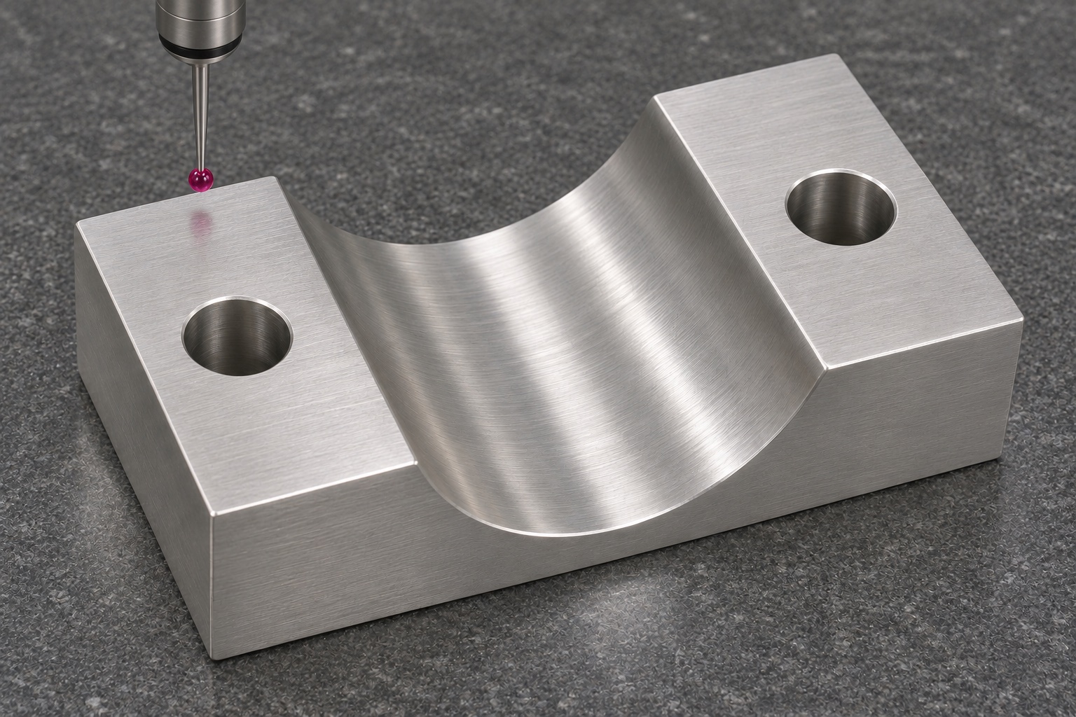
A suitable coordinate, optical or form measurement method can compare groove sections with the specified cylindrical profile. Include stations along the groove length so a local size check does not conceal taper or twist. State the datum alignment, support condition and probe access in the report. Verify ear faces and hole locations separately where the drawing requires it. A pole coupon can supplement these checks but cannot identify every geometric error. When measurement results disagree, compare reference setup and contact force before changing the part. Inspection should produce traceable evidence tied to actual characteristics, not a single unexplained pass statement.
Use an inert unloaded assembly check
Assemble the approved halves around an identified inert pole reference using the documented hardware and bench condition. Record the revisions, orientation and observed contact sequence. This check can expose interference at groove ends, mismatched ear spacing or an unexpected change during fastening. It does not prove clamping strength, equipment stability or resistance to transport loads. Do not increase torque or apply operational loads to make an uncertain fit seem acceptable. If the assembly closes unevenly, examine the mating half, fastener geometry and pole reference as well as the machined groove. The first interference should guide the investigation.
Diagnose the interface before widening the seat
If the pole touches only at one end, review groove-axis orientation, pole straightness and fixture alignment. If the ears rock on the bench support, inspect their reference surfaces and retained burrs. If the assembly changes after fastening, determine whether the hardware shifts the halves or the pole sample is outside its approved envelope. Increasing the groove radius may hide a positional error while reducing the intended contact. Document the observed condition, measured geometry and approved corrective action. Reinspect the affected features after any authorized rework. A useful trial distinguishes part conformance from an unresolved assembly design question.
Prepare an RFQ with measurable deliverables
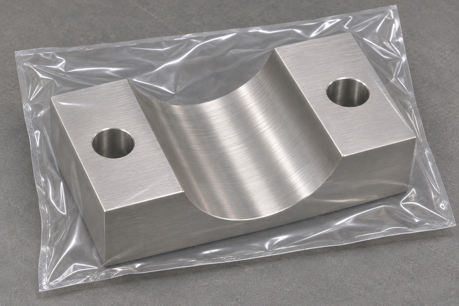
Provide the controlled drawing and CAD revision, material specification, mating-half information, pole envelope, fastener requirements, quantity, surface condition and inspection deliverables. Identify whether a separate bench-fit fixture is included and who supplies the inert pole reference. Quote special tooling and first-article reporting separately where appropriate. Protective packaging should support the body while keeping the groove and ear faces away from loose hardware and other parts. Mark packaging with revision and material identity rather than damaging functional surfaces. This defines a verifiable scope for medical equipment fixture machining while leaving complete assembly design and qualification with the responsible equipment team.
FAQ
Does a correct groove radius prove a complete clamp is safe?
No. Groove size is one characteristic. Holding force, fasteners, mating geometry and assembly qualification require separate requirements and evidence from the responsible designer.
Should both clamp ears meet when tightened?
Only if the approved design specifies that condition. Some interfaces require a controlled gap; machining should not remove it to imitate another assembly.
Can the two holes be tapped without changing the drawing?
No. This example uses plain through holes. Threads or different screw seats alter the interface and require approval before manufacture.
Why measure several sections along the seat?
Multiple sections help reveal taper, twist and local form errors that a single radius or diameter check may not detect.
Does 316L establish compatibility with cleaning chemicals?
No. The exact material, surface condition and cleaning environment must be assessed separately. The alloy name alone does not establish an approved process.
What does the inert pole fit check demonstrate?
Only the observed mechanical seating in the identified unloaded setup. It does not establish load capacity, transport stability or suitability for clinical operation.

tanghangyun@oemach.com