
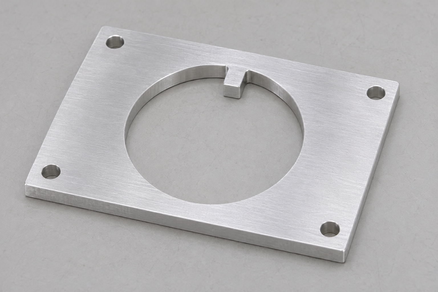
A representative mechanical fixture component
This representative machining case describes a proposed 6061 aluminum plate for a non-operating surgical microscope camera adapter bench fixture. The flat rectangular plate has one large circular through opening, one rectangular tab projecting inward at the top of that opening, and four plain corner mounting holes. It illustrates how custom CNC machining can organize feature control around a mechanical interface. It is not a report of a customer delivery, certified device, tested optical assembly or measured performance result. All dimensions, acceptance limits, finishing requirements and commercial commitments would need an approved drawing and purchase order before an actual manufacturing job could begin.

Translate the interface into drawing questions
The first review would ask how the adapter seats, which feature establishes centering, and which tab flank controls rotation. A mating slot drawing is more useful than an isolated plate model because it reveals the relationship between tab width, engagement depth and root clearance. The four corner holes would be confirmed as clearance holes rather than locating features. Any ambiguity about screw-head seating would be resolved before programming. A review should also identify whether the plate stays in a laboratory fixture or will later enter equipment qualification. That distinction changes documentation expectations without changing the need for accurate, drawing-based CNC milling.
Establish a controlled material route
The proposed starting material is 6061 aluminum in the specified temper and stock form. Material records would remain associated with the blank as it moves between operations. A saw-cut blank would include enough allowance to establish the mounting face and opposite face without assuming the incoming stock is flat. The process planner would review thickness, remaining perimeter width and likely movement before choosing the roughing sequence. No claim about sterilization, biocompatibility or medical certification follows from the alloy name. If the equipment owner needs additional material or chemical restrictions, those requirements must be stated explicitly and checked against supplier documentation.
Create the first reliable mounting reference
Initial machining would establish a reference face and suitable external edges while the blank still has adequate support. The opposite face would then be machined with a controlled thickness allowance. The planner could include a release and reclamp step before finishing to expose movement that was hidden by workholding. Final decisions would depend on the approved geometry rather than a universal stress-relief recipe. The mounting face would be protected from chips during every subsequent setup. A fixture inspection would confirm that support points are clean and that clamps do not bend the thin perimeter around the large opening into a false flat condition.
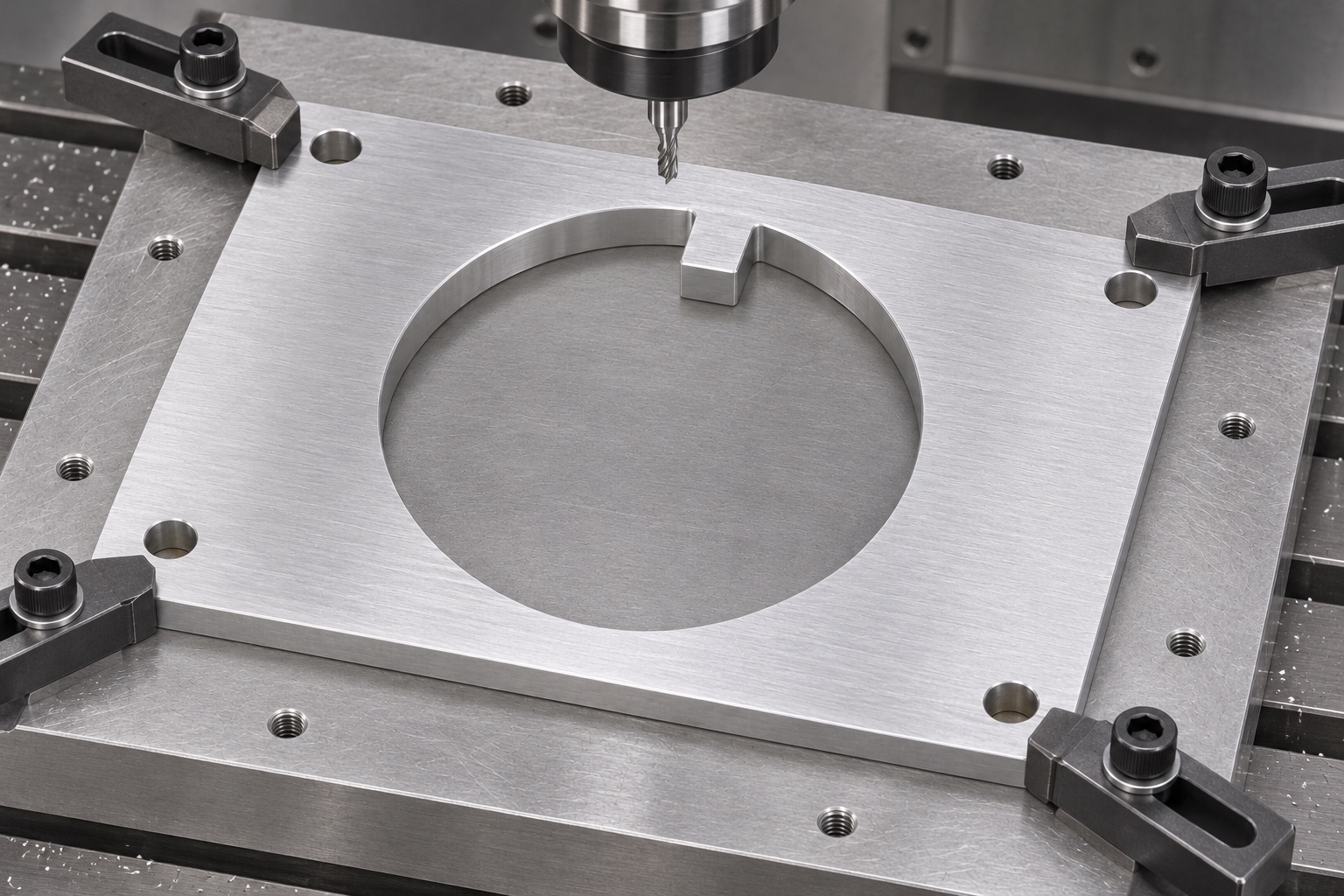
Develop a supported profile milling setup
For the large through opening, the plate could be supported on a sacrificial fixture that permits tool breakout without leaving an unsupported web. Outer clamps would hold material outside the functional profile, with their locations documented in the setup sheet. Roughing would leave a controlled finishing allowance around the circular wall and tab. Tool engagement near the tab would be reviewed separately from the open arc, since abrupt changes in cutting load can affect local geometry. This proposed CNC milling setup would be proven on an approved first piece; a plausible process plan alone does not establish that the finished plate meets its drawing.
Preserve the single integral anti-rotation tab
The tab is integral with the plate and is formed by leaving material inside the opening. Its flanks, projection and root radii would be programmed as one continuous profile. Cutter access would be checked against the mating slot envelope, particularly at the two roots. The process would not substitute a loose key or add a second tab without design approval. A careful review would distinguish a cosmetic edge break from material removal that alters engagement. If the CAD model contains an unreachable sharp internal transition, engineering would define a manufacturable radius or relief and update the controlled drawing before production.
Drill the four plain mounting holes
The proposed hole operation would locate four plain through holes from the same approved references used to define the internal profile. Hole exits would be supported where practical and inspected for burrs after breakout. The process would not add countersinks, counterbores or tapped threads by assumption. Fastener clearance and any required washer interface would be checked against the assembly information. A first-article report could document hole size and pattern location, using the exact characteristics called out by the drawing. Tightening a sample plate onto a mismatched fixture would not be accepted as evidence that the hole pattern is correct.
Define finishing and edge handling boundaries
After machining, edge finishing would remove loose burrs without rounding the tab flanks or changing the mounting face. The opening exit and small hole exits deserve specific checks because they can retain thin aluminum burrs. If an approved surface treatment is ordered, the route would identify masking requirements and the stage at which final dimensions are accepted. Appearance, coating thickness and mechanical fit are separate characteristics. The proposed route would not claim corrosion resistance, disinfectant compatibility or electrical isolation without specified requirements and supporting evidence. Cleaning would remove process residue to the agreed condition, not be described as validated sterilization.
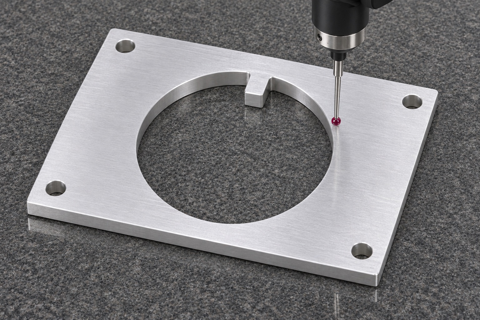
Prepare a feature-based first-article report
The proposed report would group characteristics by function: mounting-face geometry, plate thickness, external reference features, circular opening clearance, tab profile and mounting-hole pattern. Coordinate probing could be combined with optical inspection for small tab-root details. The measurement setup would state the support condition and datum alignment. Results would refer to the controlled drawing revision rather than an informal CAD screenshot. This representative example includes no invented measurement values or acceptance rate. In an actual order, measured results would be recorded only after inspection with an appropriate method, and nonconforming characteristics would require documented disposition before release.
Check assembly with a traceable dummy adapter
An unloaded dummy adapter could supplement dimensional inspection by revealing a local conflict between the tab and mating slot. The dummy revision, orientation and contact sequence would be recorded. The check would observe insertion, seating and removal without applying operational loads or using a live optical system. If interference appears, the team would identify whether it comes from tab width, root radius, slot geometry or plate seating. Hand-filing the tab until an unverified sample fits would defeat the drawing controls. A successful check would not demonstrate image quality, microscope approval or suitability for clinical operation; those remain separate responsibilities.
Control changes before a low-volume repeat order
A repeat run would retain the approved setup, tool information, finish requirements and inspection method while confirming that the drawing and mating hardware have not changed. A different adapter revision can alter tab engagement even when the plate outline appears identical. Tool replacement or fixture changes would trigger the appropriate process review rather than silent reuse of old offsets. Quote revisions would make any new inspection or finishing burden visible. Low-volume precision aluminum parts benefit from traceable decisions because small quantities do not eliminate interface risk. The purpose of the route is repeatable, reviewable manufacturing control, not a promise of unmeasured performance.
Protect the completed interface during dispatch
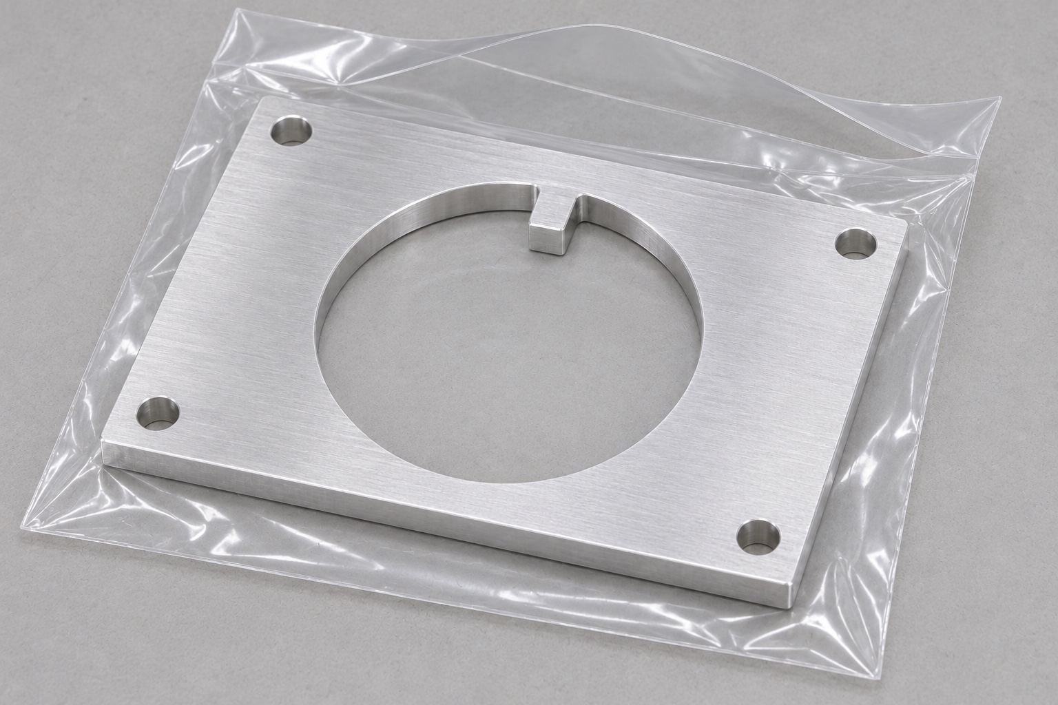
The packing proposal would separate each plate so the tab, opening edge and mounting face cannot rub against another component. Clean protective bags and suitable separators would be selected to match the order's handling requirements, without sterile labeling or unsupported cleanliness claims. The release package would identify the drawing revision, material record and agreed inspection documents. A final visual check would look for transit-sensitive edges and retained debris before sealing the protective packaging. This representative case shows the questions a supplier and equipment team should settle for custom CNC machining; it does not replace an approved design, qualification plan or actual release inspection.
FAQ
Is this a delivered customer project?
No. It is a representative machining example with a proposed route. No customer, shipment, certification or measured performance result is claimed.
What are the main features of the plate?
A flat rectangular body, one central circular opening with one inward tab, and four plain mounting holes define the representative geometry.
Why leave the tab integral with the plate?
The proposed design uses the remaining plate material to form the key. Changing to a separate key would require a different approved interface design.
Which inspection methods could be used?
Coordinate measurement can assess accessible profiles and hole patterns, while optical inspection can supplement small tab-root details. The actual method must suit the drawing.
Can finishing requirements be decided after machining?
They should be settled earlier. Coating buildup and masking can affect tab engagement, opening clearance and seating, so the process needs a defined final condition.
What documents are needed for a firm quotation?
Supply the controlled drawing and CAD revision, mating-interface information, material and temper, quantity, finish, acceptance condition, inspection deliverables and packaging requirements.

tanghangyun@oemach.com