
Define the mechanical interface before machining
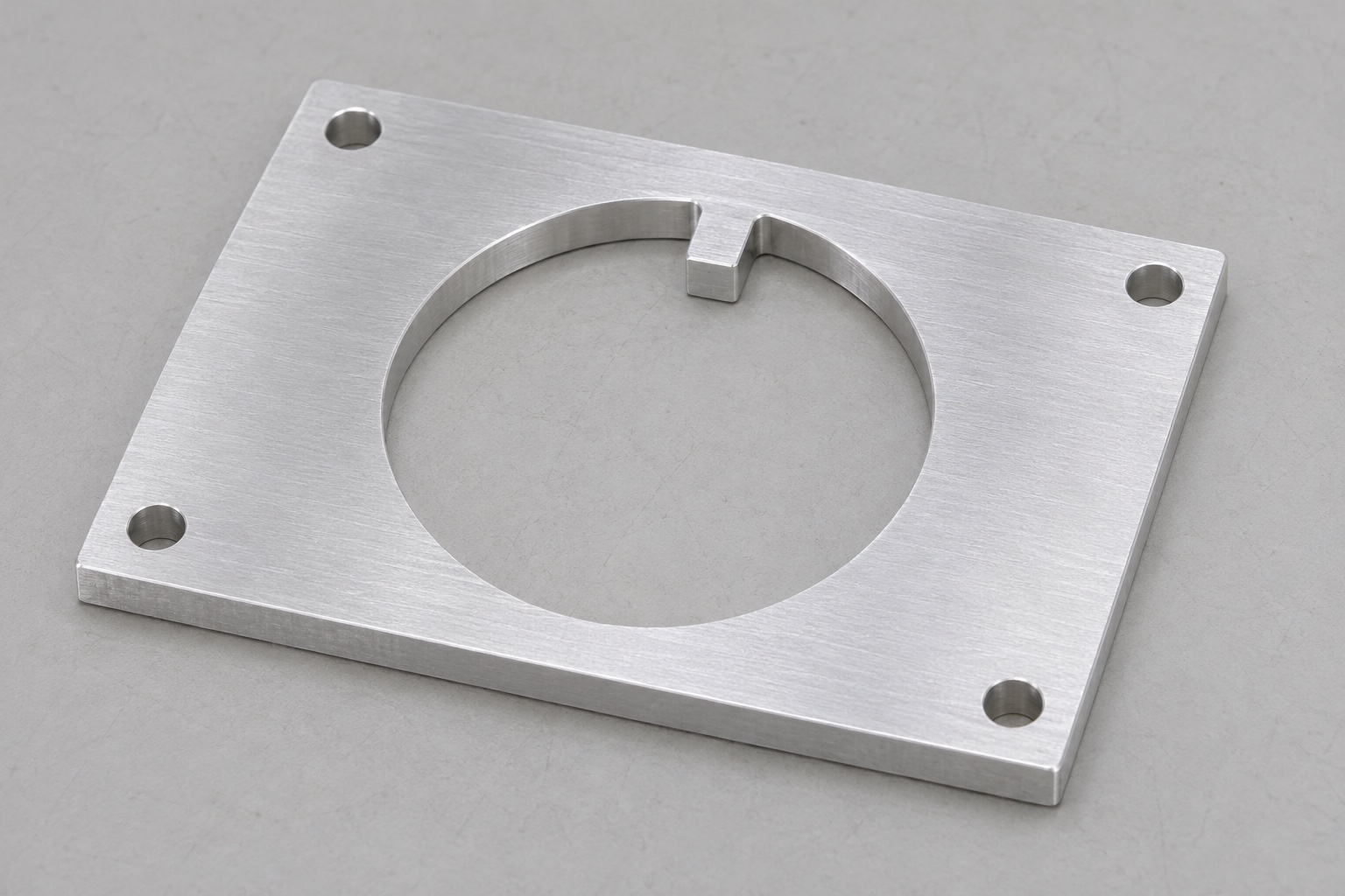
A camera adapter anti-rotation plate can look like a simple flat aluminum part, yet its locating features carry different responsibilities. The mounting face establishes axial seating, the central opening clears the adapter body, and one inward-projecting tab limits relative rotation against a corresponding slot. Four corner holes fasten the plate to a bench assembly. Precision CNC machining should start with this interface map rather than a blanket request for tight tolerances. This discussion covers a representative surgical microscope camera adapter bench fixture. It does not establish optical alignment, electrical compatibility, clinical suitability or approval for use on any named microscope.

Separate clearance from rotational location
The circular opening and the key tab must not be treated as one generic bore tolerance. An adapter may require clearance around most of its circumference while using the tab flanks to control angular play. Specify the mating cylinder envelope, slot width, engagement length and permitted assembly movement. Include any finish allowance before deciding cutter paths. A narrower slot does not automatically improve accuracy if coating, burrs or temperature prevent seating. Custom CNC machined aluminum parts need dimensions tied to their intended contact conditions, with adequate room for insertion and removal. The designer should also identify whether either tab flank is the preferred angular reference.
Build a datum scheme around seating
Use the specified mounting face as the primary reference when the assembly seats against it. A defined edge, hole pattern or circular feature can provide the remaining location only if that matches the actual assembly. Record which surface constrains rotation; do not assume the central opening both centers and keys the adapter. Flatness and parallelism requirements should be evaluated in a support condition that resembles the drawing intent. A plate that lies flat under heavy fixture clamping may spring when released. Inspection instructions should therefore describe free-state support or a defined restrained condition, including the contact points and any approved fastening sequence.
Choose 6061 stock and release stresses deliberately
6061 aluminum is a practical candidate for custom CNC milling when the drawing calls for its machinability, mass and finish options. The temper and stock form still matter. Obtain the specified grade and preserve material identification through cutting. Start with enough allowance to establish both faces without forcing a warped blank flat. Balanced roughing, intermediate release and a separate finishing operation may help manage movement, but the correct sequence depends on thickness, stock history and part geometry. Material selection does not establish a medical certification or cleaning compatibility. Those requirements belong to the component specification and the equipment owner's qualification process.
Support the plate without distorting it
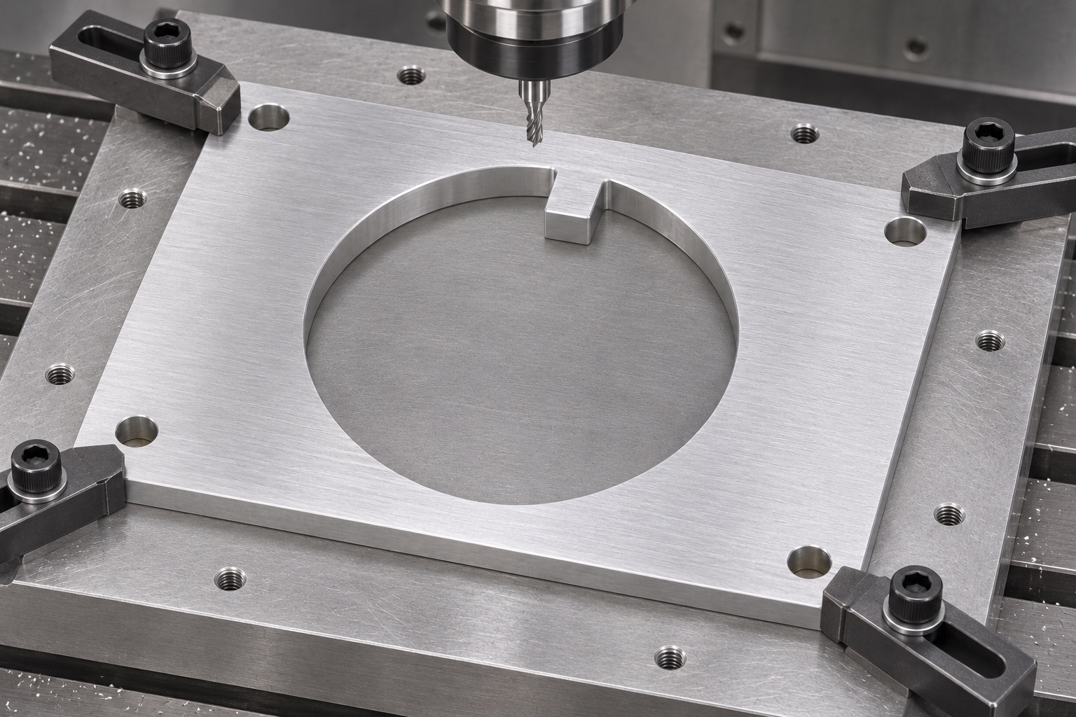
A large central opening leaves less material to resist clamping loads. Plan support beneath the remaining perimeter and choose clamp positions outside the finished contact areas. A sacrificial fixture can allow through cutting while supporting the plate, provided chips cannot become trapped beneath the seating face. Remove the part and check its relaxed condition before concluding that the fixture strategy works. For low-volume medical equipment parts machining, a simple, well-documented fixture often provides more useful control than an elaborate setup with uncertain contact. The workholding plan must also preserve tool access to the tab root and avoid cutting into clamps or mounting hardware.
Machine the keyed opening as a profile
Rough the opening with an allowance for a continuous finishing pass. The tab's inward projection is part of the internal profile, not a separate attached key. Cutter diameter limits the achievable root radii, so the mating slot must clear those radii or the drawing must provide relief. Avoid leaving a sharp, unsupported tab corner merely to match an idealized CAD silhouette. Check tool deflection at the transition from the circular wall to the tab flanks. A finishing strategy should consider both contour size and local form, because an opening can satisfy an average diameter while the tab position or root shape still blocks assembly.
Distinguish plain mounting holes from screw seats
The representative plate has four plain through holes, not countersunk or counterbored seats. Screw-head clearance and seating are supplied by the assembly design or separately specified hardware. Do not add chamfers large enough to become unintended conical seats. Locate the hole pattern from the approved datums, and state whether the holes provide clearance only or participate in positioning. Tightening screws should not be used to pull an incompatible hole pattern into place. If a drawing calls for locating dowels, that is a different feature set and requires its own fit, inspection method and assembly review rather than an informal shop-floor substitution.
Keep burr removal away from critical geometry
Break handling edges to the drawing requirement while protecting the tab flanks and seating face. An uncontrolled abrasive pass can round a small tab enough to change engagement. Inspect the opening exit edge, hole exits and root transitions under appropriate magnification. Separate deburring from final cleanliness inspection: a visually smooth edge can still carry embedded debris or residual cutting fluid. Choose cleaning materials compatible with the alloy and any specified finish. Do not describe ordinary protective cleaning as a validated medical reprocessing cycle. If a different edge treatment is needed for an assembly hazard, obtain an approved drawing change instead of improvising during finishing.
Account for surface finish before final acceptance
Anodizing or another approved finish can change the opening size, tab width and seating condition. Define whether the plate is supplied bare or finished, which surfaces are masked, and when acceptance measurements apply. Decorative appearance does not establish electrical isolation, wear life or disinfectant resistance. These properties need their own requirements and evidence. For a keyed camera adapter plate, a finish buildup at tab roots may affect fit even when the large circular clearance remains adequate. Discuss this with the finishing supplier before machining. Retain separate records for pre-finish process checks and post-finish drawing acceptance when both are part of the order.
Inspect geometry with accessible measurement paths
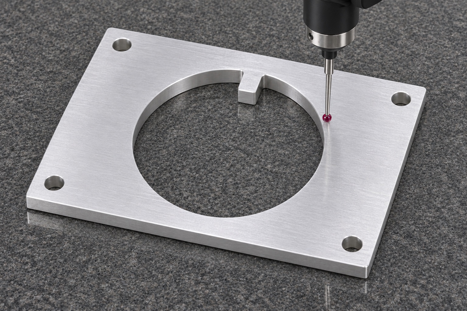
A coordinate measuring system or another qualified method can evaluate the hole pattern, opening profile and tab location relative to the mounting face. Probe size and access influence which root details can be measured directly. Supplement coordinate results with optical inspection where the tab corners are too small for reliable probing. Measure thickness and seating form in the specified support condition. Do not replace a profile requirement with a single caliper reading across the opening. Inspection planning should explain the characteristic, datum setup, instrument and reporting convention so that a later measurement can be compared meaningfully with the original acceptance record.
Use an unloaded fit check as additional evidence
A non-operating dummy adapter can help identify interference at the tab, root radii or mounting pattern. Keep the check unloaded and separate it from the controlled dimensional inspection. Record the mating dummy revision and the points of contact; an untraceable sample may itself be out of tolerance. Free insertion does not prove optical performance, image quality or safe equipment use. When engagement is poor, identify the first interference before removing material. Adjusting the entire opening to solve one local conflict can destroy the intended relationship between clearance and angular location. Engineering disposition should distinguish a part defect from an incompatible mating design.
Send a complete request for custom CNC milling
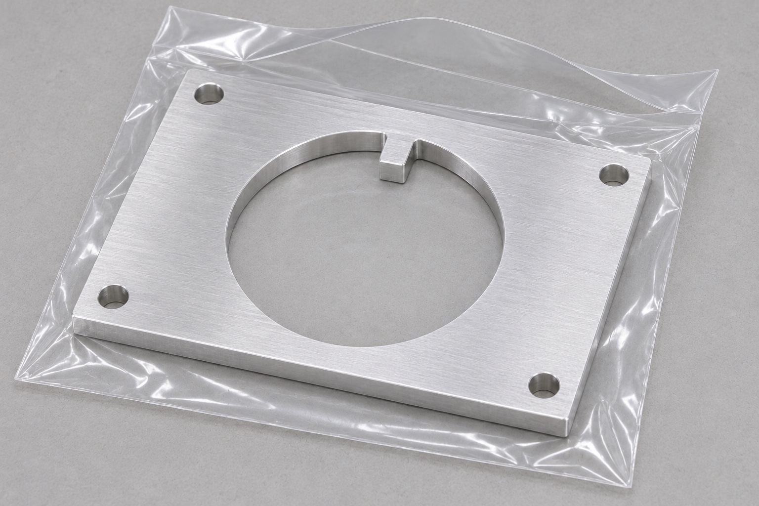
A useful quotation package contains the controlled drawing, matching CAD revision, material and temper, finished-condition tolerances, tab and slot interface information, mounting hardware requirements and inspection deliverables. State quantity, packaging preferences and whether the plate is only for a bench fixture. Identify any surface that must remain free of cosmetic handling marks. Request protective separation so tab edges and seating faces cannot rub against other parts during transport. CNC machining services can then quote the actual feature and documentation burden. Commercial acceptance should remain tied to the agreed drawing and order, not to an assumed connection between medical equipment terminology and certification.
FAQ
What does the anti-rotation tab control?
It engages a corresponding slot to limit relative rotation. Its role must be distinguished from centering clearance, axial seating and fastener retention in the assembly drawing.
Does the central opening need a precision bearing fit?
Only if the approved design requires it. Many keyed interfaces need circumferential clearance while tab flanks provide angular location; do not impose a bearing fit automatically.
Can the four mounting holes be countersunk by default?
No. This plate uses plain through holes. Add a countersink only through an approved drawing or order requirement with matching screw geometry.
Why inspect the plate after unclamping?
Clamping can temporarily flatten a thin plate. Released-state or specified restrained measurements reveal whether the supplied geometry meets the intended seating condition.
Should the tab be inspected before or after anodizing?
Follow the order's acceptance condition. If finishing is specified, account for buildup and masking, and verify relevant final dimensions after finishing.
Does a successful bench fit prove microscope compatibility?
No. An unloaded fit check only supplements mechanical inspection. Optical, electrical, operational and clinical compatibility require separate evaluation by the responsible equipment team.

tanghangyun@oemach.com