
Separate mechanical location from optical qualification
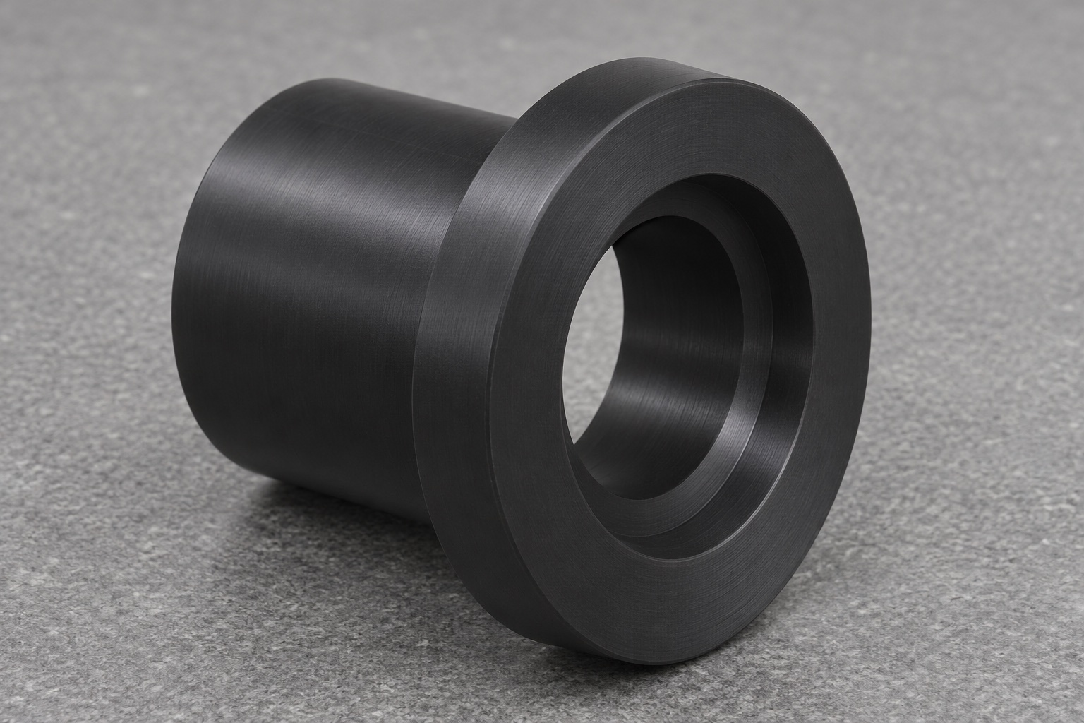
An enclosed engineering test fixture for a dental curing light may use a black PEEK sleeve to locate a removable adapter and define an opening near the instrument axis. The example has a flange, a short external locating diameter and two coaxial bore steps. The flange seats against the fixture carrier; the bore clears a non-operating tip surrogate and provides a defined aperture. Color is not evidence of optical attenuation or surface scatter. This guide concerns machining and inspection of sleeve geometry only, not light dosage, eye protection, curing performance or use on a patient.

Decide where the adapter actually contacts
Show the mating carrier, intended flange seat and usable length of the locating diameter in section. A tip surrogate should not touch the effective aperture unless the design intentionally defines that contact. The bore may include a larger entry and a smaller downstream opening, with the shoulder located away from sensitive faces. If the inner step is a clearance feature, do not use it as the sole reference for the flange. Indicate which edge is nearest the source and in which direction the sleeve is fitted. These details prevent the shop from finishing the correct diameter in the wrong axial position.
Relate the bore steps to the locating surface
Define the main axis from the outer pilot or another drawing-approved reference. If clear aperture depends on centering, control the bore relationship to that axis and not just its diameter. A good through fit on a small pin can coexist with an eccentric opening. Specify the allowable seated distance and usable length of both bore sections. Review the smallest remaining wall where inside and outside features overlap. Do not use a runout number without identifying where it applies and what surface establishes rotation. The flange also needs a face relationship that preserves the intended orientation after assembly.
Turn a supported blank in a stable order
Use the approved grade, color and stock form. Identify material before machining, as two black polymer rods need not have the same composition or behavior. Face the blank and rough the inner and outer geometry with enough support remaining around the sleeve. Where practical, finish the critical bore steps and outer pilot before moving the part to another setup. Use sharp tools, controlled engagement and chip evacuation so a long strand does not scratch the bore or block visibility. Confirm access and stiffness for the step at its actual depth. Inspect after release rather than interpreting a hot, clamped reading as final.
Manage clamping and temperature explicitly
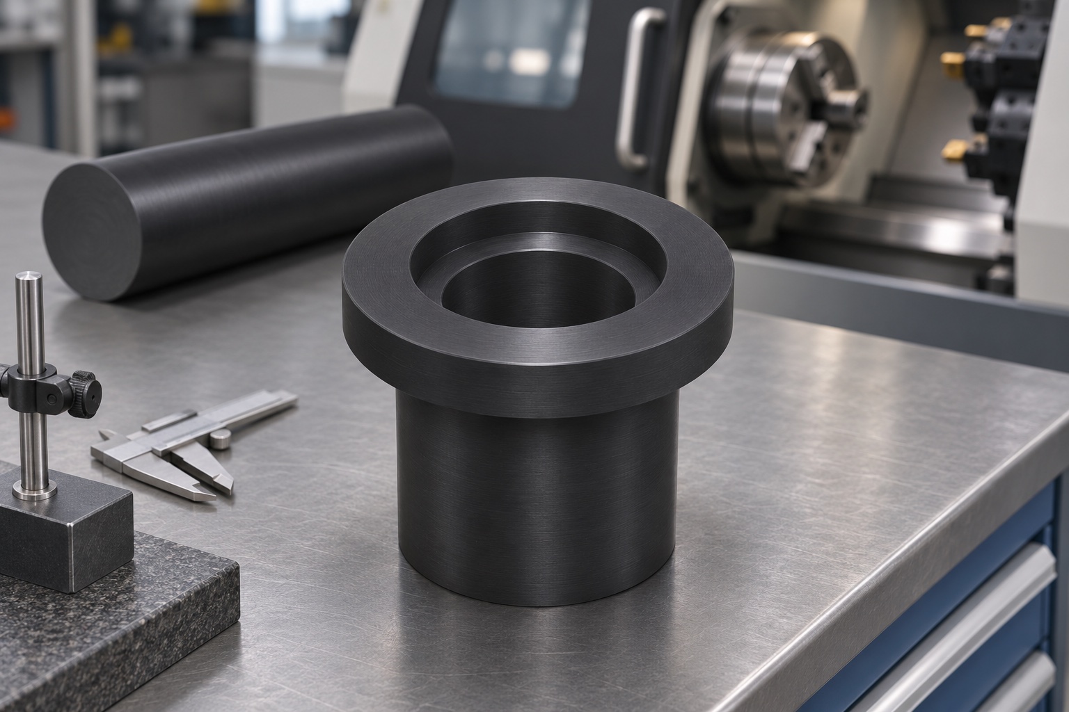
Jaw pressure can temporarily change a thin polymer wall. A diameter that looks round on the lathe may show a different shape after release. Use a suitable collet, soft jaws or evenly supported fixture and keep the clamp band away from the aperture and thin transition. Monitor the first piece after it settles at the specified inspection condition. For tight limits, define part and instrument stabilization and record any relevant temperatures. Do not compensate size against a freshly machined piece without understanding the change. If material removal causes movement, compare a revised roughing and finishing sequence on the pilot.
Finish the step without reducing the opening
A rounded edge or burr near the narrow opening affects the usable aperture even when a nominal diameter is correct. Break handling edges only as specified. Keep the shoulder flat where it acts as a stop and inspect both sides of the step for hanging plastic strands. A broad polish can change the opening, increase gloss or leave trapped residue. If the owner specifies a texture for optical reasons, document the required method and identify which surface receives it. No optical behavior should be inferred from a photograph or color. Verify the approved finish separately from basic fit geometry.
Choose an inspection method with low force
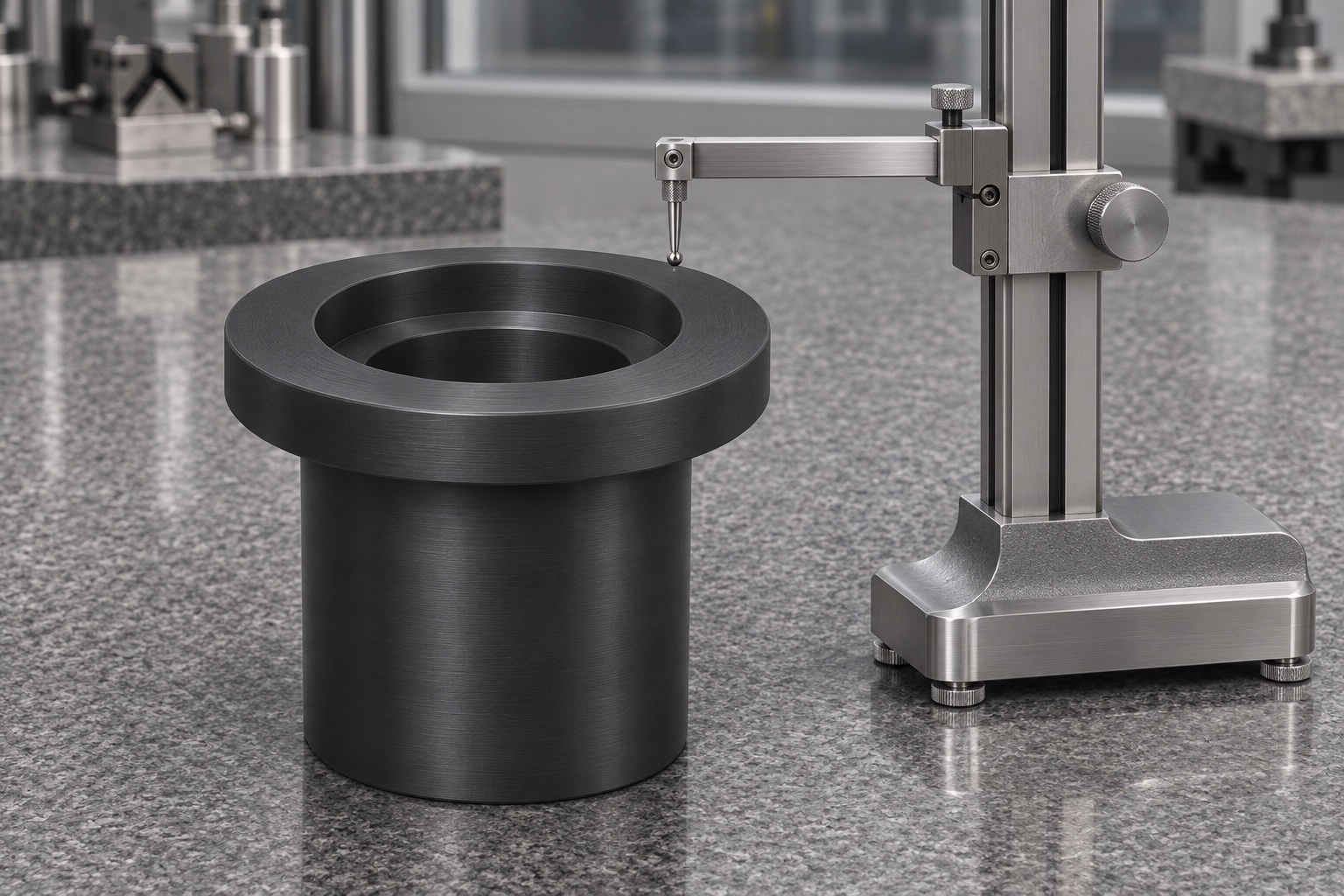
Measure the outer pilot, flange and both bore sizes from the references in the drawing. Select contact methods with force low enough to avoid moving or deforming the sleeve, or use suitable optical measurement where the section is visible. For a stepped bore, focus and illumination can shift the apparent boundary. A top view cannot establish inner shoulder depth by itself. Use a qualified depth or sectional method and record the instrument and measurement plane. Avoid forcing a gauge through a soft edge. A report should distinguish a dimensional result from a functional passage check and state the stabilization condition.
Verify the opening at assembly limits
Assemble on a non-operating fixture with an approved dummy adapter. Check the flange seat and confirm clearance at both ends of the bore. Use a dummy tip with the defined maximum envelope where relevant. Inspect for interference during insertion and removal and note its location. If the smaller opening lies off the nominal axis, determine whether the sleeve pilot, flange seat or fixture contributes before changing the bore. Measure the assembled distance if the design depends on axial placement. This mechanical check does not replace an optical study with a verified source, detector and protected measurement setup.
Troubleshoot the observed failure mode
If the flange seats but the dummy tip rubs, compare the bore center with the pilot and inspect the step for raised material. If the pilot fits but the flange rocks, verify the fixture shoulder and edge radii. If a free bore measures correctly and tightens only when installed, investigate the clamp or retention mechanism. Inspect the entire usable engagement, not the first few millimeters. Hold any part with an unexplained defect and repeat the test under documented conditions. A correction should address the cause, not merely make one sample enter when it is pressed into the fixture.
Define what a quotation must include
Send the drawing and fixture section, PEEK grade, approved finish and required inspection condition. State which diameter locates the sleeve and which opening must remain clear. Ask for first-article evidence covering bore centers, axial step depth, flange seat and pilot size as needed. Identify any explicit optical test outside the part scope and which organization would run it. If a fit fixture is required, state who supplies it and whether it is included in the quote. Compare low-volume CNC turning routes using the same gauge, datum and accepted part condition rather than nominal dimensions alone.
Preserve the result through repeat production
Record the blank identity, roughing order, tool edge condition, grip method and final measurement details for the approved pilot. A change in stock grade or clamping should trigger a review of roundness and seat geometry. If the opening is screened by a master, maintain records of that reference and verify wear. An approved first piece does not establish long-term process capability. Define the sampling and recheck plan separately. Where finish matters, preserve photos or measured finish data only when they reflect the actual accepted specification. Keep the fixture assembly revision linked to any mechanical fit record.
Avoid pressure on the flange and aperture
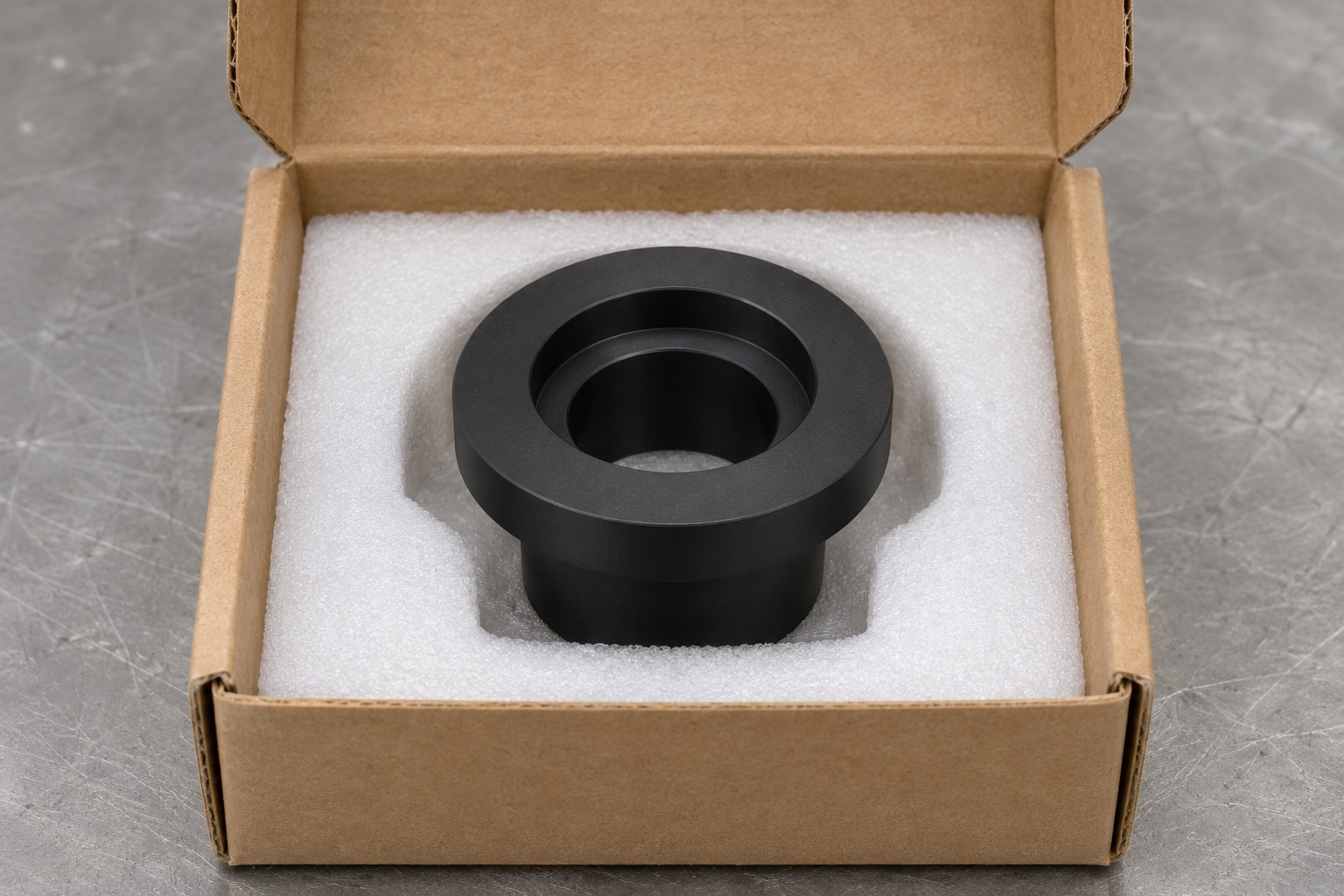
Pack the sleeve in an individual recess supporting its rigid body, with room around the flange and bore mouth. Do not insert loose metal pins or paperwork into the bore. Keep the parts clean to the agreed handling condition and identify them on the outside of their package. Avoid squeezing a thin section in a tight insert. This is transport protection, not sterile packaging. At receiving, examine the shoulder and bore edges and let the part stabilize before repeating close measurements. A part with impact or pressure marks should be assessed before it is installed in a fixture.
FAQ
Does black PEEK guarantee a light-tight assembly?
No. Color alone does not establish transmission, reflection or assembled leakage. Define and verify those properties separately if needed.
Why specify the flange seat as well as bore size?
The flange controls axial position. A compliant bore cannot compensate for a seat that tilts the sleeve or moves the opening along the axis.
Can a plug gauge verify coaxiality?
Not by itself. Use an agreed datum and measurement method for the relationship between the pilot and both bore axes.
Why measure after the sleeve has cooled?
Temperature and gripping forces can affect the shape of a polymer. Final acceptance should use the specified, repeatable measurement condition.
Will a matte hand finish improve optical behavior?
Not necessarily. It can alter geometry and optical response. Apply only a defined finish and have the equipment owner evaluate any optical requirement.
Is this sleeve a protective device?
No. The example is a fixture component. It does not establish eye protection, treatment output or clinical suitability.

tanghangyun@oemach.com