
Define the support before sizing the groove
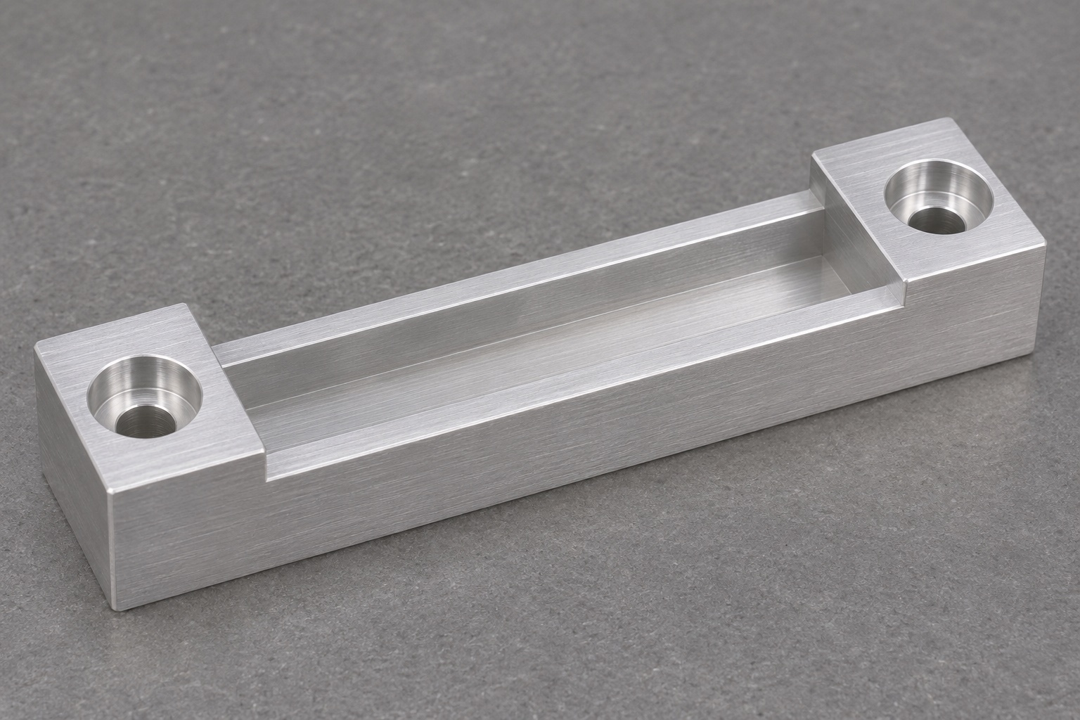
A removable splash guard on a laboratory microplate washer can use a small support shoe to capture its lower edge. The example here is a 6061 aluminum block with a straight top groove between two mounting bosses and a counterbored through hole in each boss. The groove locates the guard edge; the screws attach the shoe to a stationary bracket. Neither the shoe nor this machining plan establishes containment or cleaning performance. Treat it as a mechanical development part outside the fluid path. Define where the guard rests, how it is inserted and which surfaces are intentionally clear.

Specify the shape of the mating edge
Obtain the guard edge thickness range and an outline of the portion that enters the groove. Include any fold, edge trim or protective film that remains in service. A nominal flat coupon may fail to represent the thickest finished edge. Define whether the edge should seat on the floor or on a separate shoulder. Check the intended removal direction and identify nearby covers that could restrict access. If the guard is supposed to lift out vertically, clearance at the groove ends may only protect its outline rather than guide insertion. This distinction sets reasonable dimensional priorities.
Establish the base as the working reference
If the shoe attaches to a machined bracket, use its underside as the primary seating reference. Define the location of the groove relative to that surface and to the side or end features that position the shoe. Screw clearance holes normally provide attachment rather than repeatable lateral location. If mounting adjustment is intentional, state the direction and usable range. Avoid using a cosmetic outer face as a datum when the assembly never contacts it. Give the shop the working section so it can measure slot depth from the right surface rather than relying on the overall block thickness alone.
Rough the slot under distributed support
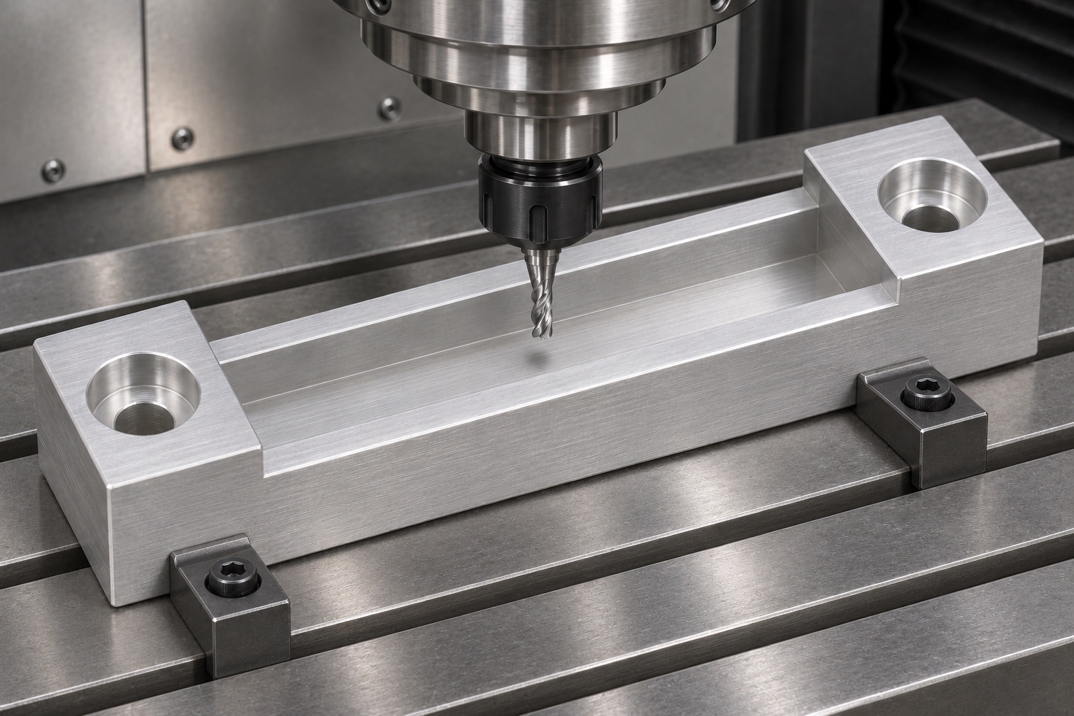
Precision 6061 CNC milling starts with the specified stock condition and a fixture that supports the base along its working length. Check the reference surfaces for trapped chips. Rough the groove in stages and retain stock for separate floor and wall passes. If the rails at either side are slender, avoid pushing them against the cutter or each other. Begin with a cutter that has room to clear chips and reach the specified root radius. An undersized tool can leave room to finish the walls independently, but a long overhang can also produce taper. Measure the result after release.
Match the corner and end clearances
The intersection of groove wall and floor is not infinitely sharp. Specify a tool radius or relief compatible with the edge geometry rather than requiring a square internal corner without a reason. A rigid guard can bridge a root radius and appear to have insufficient depth even when the center of the floor is correct. Check the useful length between the bosses and keep cutter entry marks away from any seating zone. Inspect the ends under angled light. Do not blend a transition by hand if it changes a controlled stop. Resolve a corner conflict by agreement before machining production pieces.
Set the counterbore from the mounting stack
Both screw heads need enough clearance from the guard and any nearby cover. A counterbore depth from the top of a boss may not directly control the exposed head height if the actual screw differs from the drawing. Specify the screw envelope and seat condition as well as the hole size. Check the remaining thickness below the counterbore when considering a depth change. Burrs on the underside of the through holes can tilt the shoe. Remove them without producing a hollow around a working support point. Inspect representative hardware only under the condition agreed for the fixture.
Review finish and handling separately
If the design calls for an anodized finish, identify how the groove and mounting surfaces are treated and which post-finish dimensions must be checked. Agree on masked areas where fit demands it. An arbitrary oversize allowance is not a substitute for understanding the finish route. For an as-machined part, specify surface texture and edge condition at the guard contact. Keep chips or abrasive residue out of the pocket and through holes. The chosen alloy and surface finish do not make the part compatible with every liquid formulation or disinfectant. Those conditions require separate approval by the equipment owner.
Measure the groove across its working length
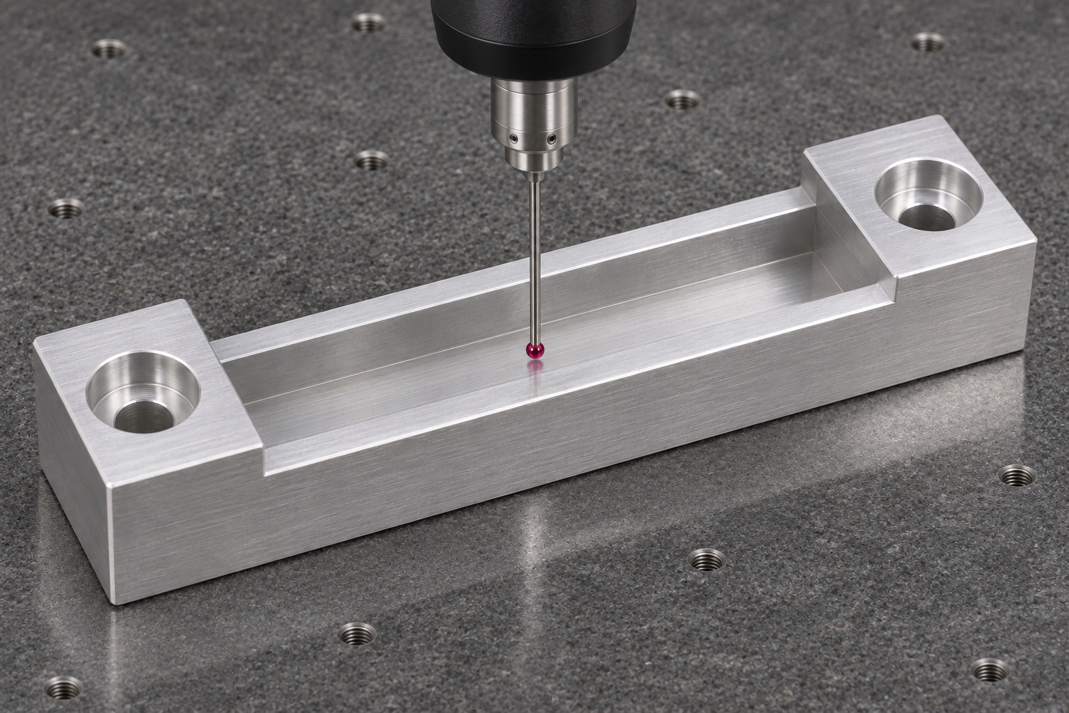
Check the width between the straight walls at multiple locations and agreed depths. A caliper at the entrance may miss narrowing lower down. Inspect floor height relative to the base and capture enough points to distinguish slope from a single local mark. Use a suitable coordinate measuring probe or alternate calibrated method if access is limited. Inspect the counterbore seat and verify screw-head clearance with a controlled example where specified. Document the measurement arrangement and whether the shoe is supported free or restrained. An undersized gauge coupon can slide smoothly while both width and depth are wrong.
Use a dummy guard for assembly checks
Mount the shoe on a non-operational bracket with the specified hardware. Insert a clean dummy guard representing the agreed envelope and note where it first contacts. Check intended seating, removal and clearance to screw heads and other structures. If installation depends on a particular tightening order, document it. A part that fits before tightening but sticks afterward may be deflected by the bracket or mounted against a burr. Compare both conditions before machining more clearance. This trial checks mechanical interfaces only. It does not validate splash containment, fluid compatibility, hygiene, diagnostics or the operation of a washer.
Diagnose failures by contact evidence
If the guard enters at one end and stops at the other, compare groove width and the dummy edge over the same locations. If it rocks at full insertion, examine the floor, root radius and bottom edge shape. If it drags against a screw, verify the head and seat before changing the groove. Use a drawing-approved witness method where appropriate and clean the part afterward. Document the observed contact instead of recording only that the guard felt tight. A small release test with the same coupon and bracket can distinguish a setup correction from an accidental fit on one piece.
Specify the pilot and inspection deliverables
Provide the alloy temper, drawing revision, guard edge envelope and fastener data with the quote request. Ask for slot width at defined stations, floor height and the fastener seats in the first-article report. If fit must be checked after coating, include the finish condition in the accepted scope. Separate the cost of a bench fixture or special gauge from the price of milled parts. A simple support shoe may be economical in small lots, but there is no useful comparison between quotes unless both include the same inspection evidence. Retain an approved reference coupon where the drawing calls for one.
Pack to keep the slot edges intact
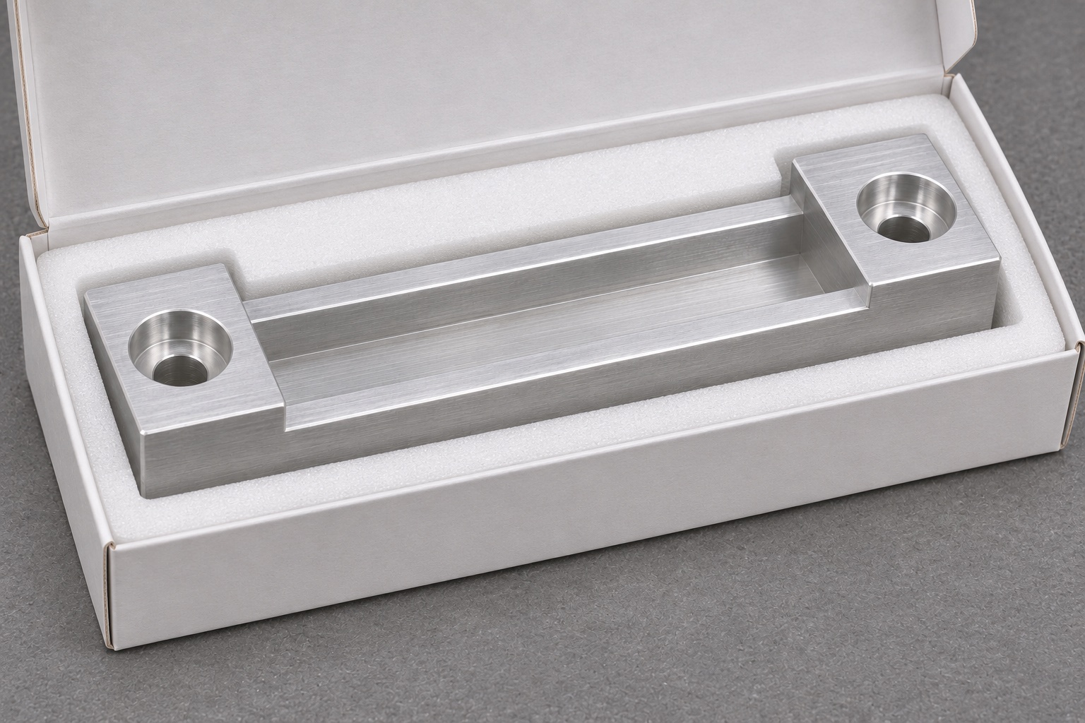
Ship each shoe flat in a fitted pocket or separated by a clean non-abrasive layer. Leave space for the groove edges so they do not scrape a rigid tray and keep the screws in a separate compartment. Link the inspection record to the material lot and drawing revision. Avoid pressure on a narrow rail during storage. This is transit protection, not sterile packaging. At receipt, examine the groove, screw seats and base under good light. If there is visible impact or debris, repeat the affected measurements or clean by the agreed process before performing the bench fit.
FAQ
Why sample groove width at more than one station?
An end measurement can miss taper, tool deflection or a local high spot. Sample across the functional length and at the agreed depths.
Does a nominal guard coupon show the worst fit?
No. It represents one condition. Check the released thickness range, retained trim and allowed variations in the seating edge.
Why use counterbores instead of countersinks?
The recess must match the specified screw head and bearing geometry. One feature cannot be substituted for the other without reviewing the mounting design.
Can anodizing affect the fit?
It can change fit on working surfaces. Agree on masking and inspect dimensions in the required final state rather than assuming the allowance.
Is the shoe a wash-fluid component?
Not in this example. It locates a removable mechanical guard. The equipment owner must verify any exposure and compatibility requirements separately.
Is a successful fit check proof of containment?
No. The check addresses seating, removal and clearance in a bench fixture. It is not a washer performance or safety test.

tanghangyun@oemach.com