
Define what the master checks
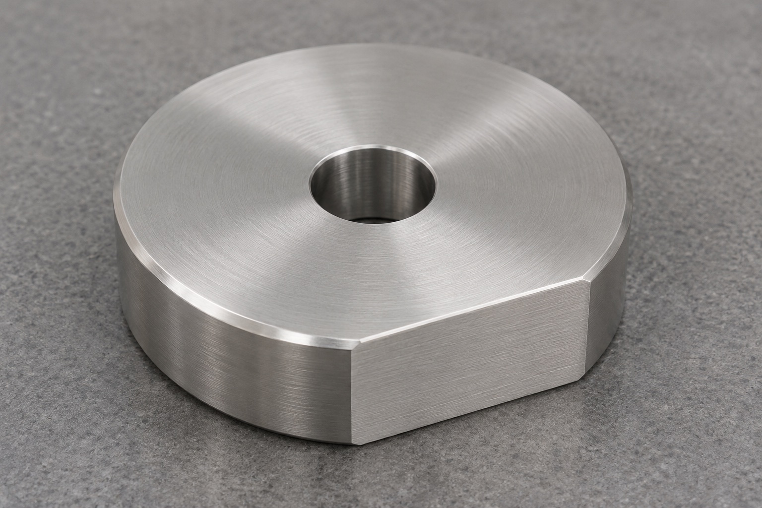
A development bench for a radiotherapy positioning rail can use a machined indexing master to check whether a dummy nest presents the expected seating, center and orientation. The example is a 316L disk with one through bore and one chord flat. Its underside seats on a stop, the bore engages a reference pin and the flat faces a directional stop. This is an off-device fixture aid, not a patient positioning accessory or a calibration device for treatment. Precision CNC machining starts by confirming exactly which contacts are active and which surfaces only need clearance.

Choose datums from contact order
When the disk seats first on its underside, that face can establish the primary datum. The center bore establishes an axis and the flat can remove the remaining rotation around it. Make the seating sequence explicit, including if the fixture contacts the flat only after the bore has entered. The outside diameter may be a clearance envelope rather than a locating feature. Referencing all dimensions to the outside cylinder would then leave a gap in the inspection plan. Coordinate the pin fit, edge breaks and effective bore length so the part can actually reproduce the intended contact order.
Separate flat distance from flat direction
The shortest distance from the bore axis to the flat controls its radial position. Direction may also matter if another feature defines angular orientation, but a disk with one bore and one flat has no independent angular reference about the bore. Avoid specifying a redundant angle to an arbitrary edge. Instead, define the relationship between the flat and seating face and, where needed, supply a reference for face orientation on the drawing. Measure the machined flat away from corner breaks. A rough width across the chord is not a substitute for offset because it also depends on the outside diameter.
Turn the bore and seating face first
Choose the released 316L bar condition and keep material identification tied to the blank. A stable turning setup can finish the working face and bore without removing and replacing the blank. Plan access for the boring tool and leave clearance at the far side. Do not count the lead-in chamfer as usable bore engagement. Check if the bore depends on a reaming operation, a finished boring pass or another qualified method. Keep the tool engaged cleanly, remove chips from the bore and check the first piece cold. Excess clamping can deform even a short disk if the walls are thin.
Transfer the actual bore center to milling
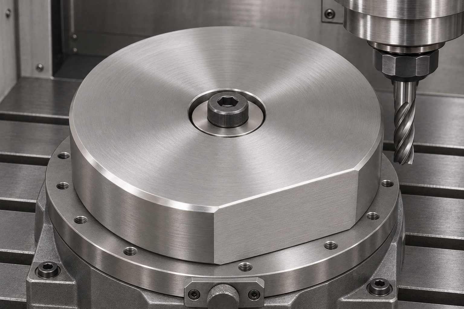
Set the disk on its reference face and locate it on a controlled arbor or other bore-referenced fixture. Clamp against the support rather than bending the disk across a gap. If the arbor needs clearance for loading, determine how its fit or a probing routine affects center repeatability. A three-jaw grip on the outside diameter may introduce a radial error even when the outside looks true. Establish the required flat location from the measured axis and use a stable cutter path. Keep the disk still during cutting, but avoid leaving impressions on the face used to seat the master.
Control edges at the flat transitions
The edges at the two ends of the chord flat can mark a mating stop or catch on a protective cover. Define an edge break that removes raised material without shortening the useful contact region. The bore can also retain a raised lip where the tool exits. Inspect the entry and exit separately. Use clean stainless-compatible tools and keep loose abrasives away from the bore and face. If passivation is specified, agree on the scope, route and final inspection state. Do not assume that a given steel designation defines all cleaning, finish or packaging requirements for the fixture.
Distinguish form from assembly fit
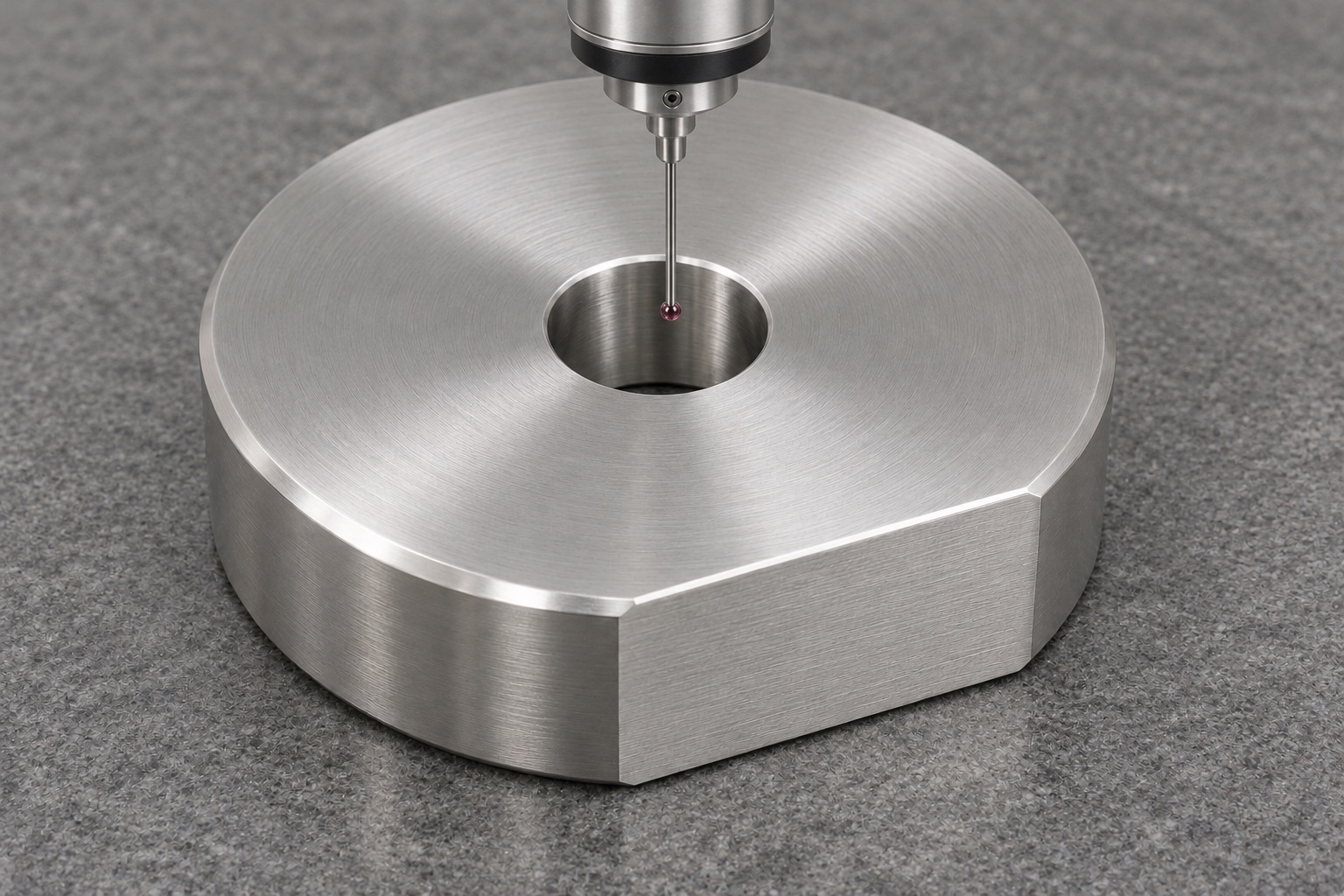
A plug gauge can confirm basic hole passage or size as defined by the drawing. It does not verify bore orientation to the seat or the flat offset. In a coordinate measurement setup, sample the seating face, several accessible depths in the bore and the working flat. Avoid chamfers and define whether a fitted or functional axis is required. Check fixture pressure during a repeat reading. Use a direct surface measurement if the contact band or flatness needs more information than a few touch points can supply. Record the support condition and instrument uncertainty if it affects a close acceptance decision.
Check insertion in a non-operational rail fixture
An approved bench fixture can reproduce the reference pin and directional stop. Assemble the clean master without forcing it. Check whether it reaches the face before the flat binds and whether it can be removed without scraping. Repeat at agreed clearance limits or demonstrate that the gauge represents those limits. If the master seats when the directional stop is absent, measure flat offset and stop alignment before changing bore size. Log the fixture revision and the condition tested. This is a mechanical interface screen and does not establish clinical alignment, motion safety, imaging performance or delivered dose.
Investigate inconsistent readings methodically
If the flat is offset by a similar amount across pilot pieces, check the milling locator and coordinate setup. If the error changes when the disk is rotated or reclamped, inspect the fixture fit and seating debris. If size passes but the part rocks, check for an underside burr or a bowed seating face. When the disk enters the fixture but stops after a short travel, verify the pin lead-in and bore engagement. Separate contact evidence from an operator's impression of tightness. A useful corrective record identifies the exact feature, condition and instrument that confirmed the cause.
Plan records for repeat orders
A first-article package can include stock lot, drawing revision, seating face, bore size and orientation, flat offset and the bench gauge identification. Define the required readings rather than asking for an unspecified precision check. If a trial compares turn-mill and separate turning and milling, use the same acceptance setup for both. Record how the datum is transferred; this is often more relevant to the result than machine axis count. For repeat low-volume machining, list changes that require a first-piece recheck, such as arbor replacement or a new finish route. Do not infer batch capability from one well-fitting sample.
Keep the master distinct from production gauges
Give the master a controlled identity on its package or on a permitted non-functional surface. Do not hand mark the working face or flat without approval. Keep an inspection record that distinguishes the actual measured values from new nominal dimensions. If a master is intended to verify other gauges, define its verification interval and handling procedure separately. A newly machined part is not automatically a traceable calibration reference. Store the drawing, fixture notes and measured results together, and review damage or wear before using an older master to make acceptance judgments about a fixture.
Protect seating surfaces in shipping
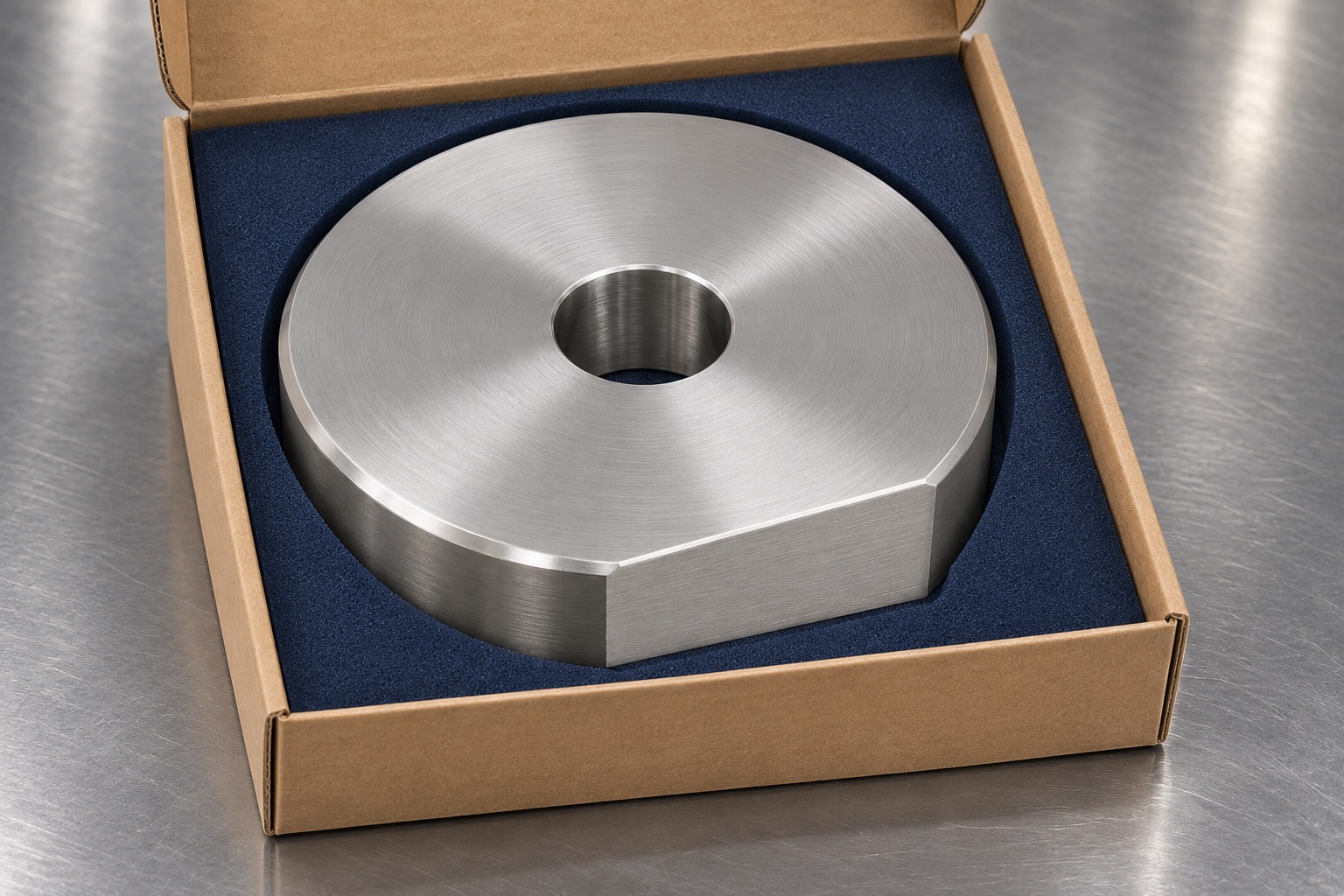
Use a fitted recess with broad support and space around the chord flat. Keep other metal components separate so they cannot dent the bore mouth or seat. Prevent grit from entering the bore and use the protection required by the agreed purchase specification. Link the outer label to the stock lot and drawing revision. This is ordinary handling protection, not a sterile package. At receipt, examine the face, bore openings and chord ends under suitable light. If a package has shifted or a contact face is damaged, repeat the relevant measurements before relying on the master.
FAQ
Can an outside diameter locate the milling operation?
Only if its relationship to the bore is controlled and the fixture uses it as intended. Otherwise locate from the bore or use a verified probing method.
Does chord width give the flat offset?
Not by itself. The same chord width can imply different offsets at different outside diameters. Measure from the required axis to the flat.
Why measure the bore at several depths?
Multiple depths help reveal taper or an axis error. Keep probe points clear of the chamfer and use the drawing's specified fit method.
Is a plug check enough for the master?
No. It is useful for a defined bore check but does not establish the seating face, axis orientation or flat location.
Does the fixture check calibrate a radiotherapy system?
No. It checks stated mechanical interfaces of a non-operational bench fixture only. It does not verify patient alignment or treatment performance.
How can transit damage affect the result?
A dent or burr at a datum can prevent full seating even if other dimensions pass. Inspect the contacts and remeasure any affected feature.

tanghangyun@oemach.com