
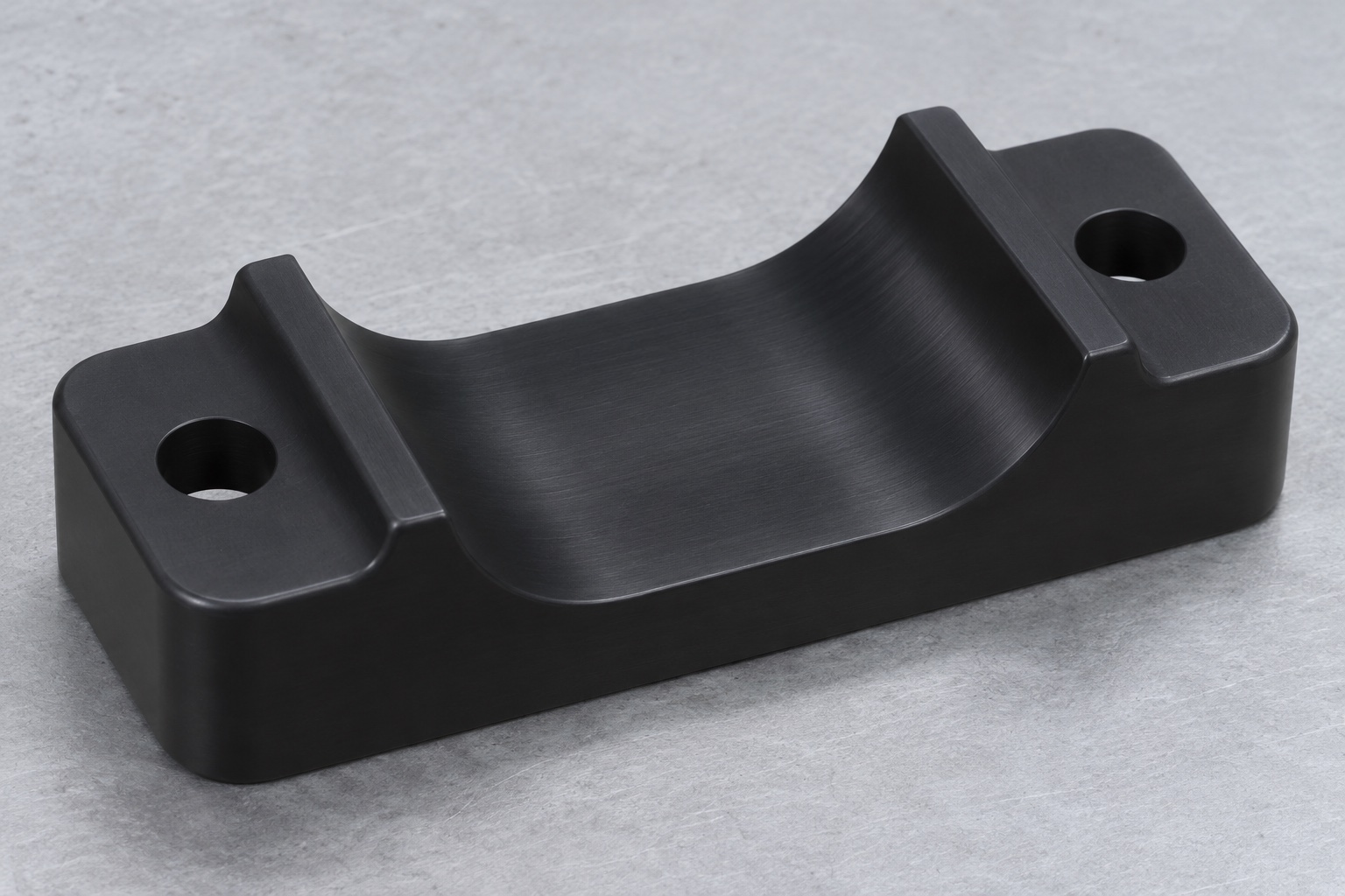
Identify what the cradle supports
A closed-tube mixer mechanism in a hematology analyzer may use a machined saddle to support a tube body while a separate retainer holds it in place. In this example a shallow, open curved channel spans the center of a black POM-C block. Two through holes attach the block to a moving carrier. The saddle is a mechanical support, not a complete retaining system. Define which tube body region may rest on the arc, and keep the cap, label boundaries and neighboring components clear where the equipment design requires it. The discussion covers component machining, not clinical sample preparation.

Work from the tube envelope
Ask for the allowed outside diameter, straight body length and cap envelope. Include any permitted seam, taper or label thickness where it crosses the support. A single nominal cylinder cannot reveal all possible interferences. Define the support band in a sectional view and clarify where the cap and tube end can overhang the open channel. Treat the clearance to the separate retainer and actuator as assembly inputs. A channel that fits one clean dummy tube may bind when a boundary condition is added. Use controlled geometry or representative gauges, not a collection of undocumented tubes of different origins.
Control seated height as well as radius
The bottom face of the saddle can establish the working datum. The depth and profile of the contact arc determine how a tube sits relative to that face. The radius alone does not establish the tube center height. Draw the full section and specify the inspection regions that matter. If mounting screw holes allow clearance, define how the part is located in plane. A lateral edge or an assembly fixture can provide the missing reference. Keep screw heads clear of the contact band and check the height after assembly when fastener load can change the shape of the part.
Machine from a supported polymer blank
Use the specified POM-C grade and stock form and retain the lot identity. Support the bottom face and keep clamps on the wings or temporary stock, not on the thin region below the channel. Rough the arc in stages, leaving a controlled finish allowance. A sharp cutter with chip space helps prevent rubbing and dragging warm chips into the contact region. Consider balanced face cuts if the blank moves after one-sided stock removal. Compare the geometry in and out of the fixture before trusting the setup. A rigid fixture should support the part without forcing it into a false flat shape.
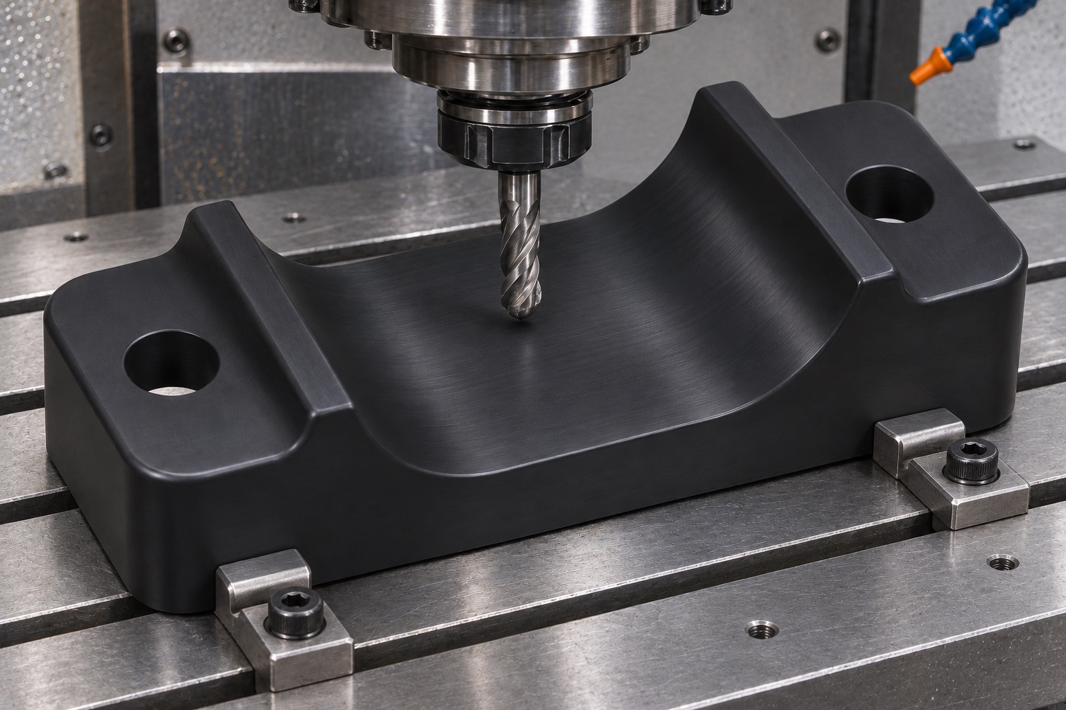
Finish the open arc without leaving a ridge
For a small run, a ball-end tool can generate the profile if the toolpath, engagement and step-over meet the required surface. A form tool may be considered where the geometry, cutting load and inspection method make it practical. Keep lead-ins and exits away from the most critical contact region. Check the two open ends for ridges and the center for a high strip. These features can lift a tube even if a small part of the arc looks correct. Verify the finish on a pilot before changing the tool path across the lot. Do not smooth the profile by eye after acceptance.
Treat the edges as part of the contact design
Specify the allowed breaks at the channel lips, mounting-hole exits and handling edges. A filament of plastic can scratch a tube surrogate or prevent it from fully seating. A large edge rounding can shorten the effective contact band. Inspect under appropriate light and magnification, especially on black stock. Remove loose material with a method that does not change the profile. Clean and dry the component as agreed, and keep it away from abrasives and mixed swarf. If a specific detergent, reagent or residue limit matters, confirm it separately with the equipment owner rather than assuming compatibility from the polymer name.
Check the part after it stabilizes
POM-C part geometry can vary with temperature and with clamp or probe force. Define the measurement condition for close features, including how the component rests and whether it is restrained. Let the machined piece stabilize before final inspection when required. A broad base reference helps, provided the support does not rock or lift the wings. If comparing measurements before and after assembly, record fastener condition and support geometry. A feature that appears to move can be reacting to an inconsistent test rather than to machining error. Confirm repeatability of the method before changing a compensated tool path.
Measure the arc and tube center in distinct checks
Use suitable optical profile measurements at accessible sections or a qualified tactile measurement with low enough force. A profile view of an open end does not establish the geometry along the full contact band. Select additional locations or a scan where necessary. Compare the measured arc to the drawing and check the actual seat height with a clean cylindrical master of known diameter if specified. Document the gauge diameter and support state. A master that sits at the right height can still hide isolated high spots or uneven contact. Use the direct geometry and fit observations together to diagnose the cause.
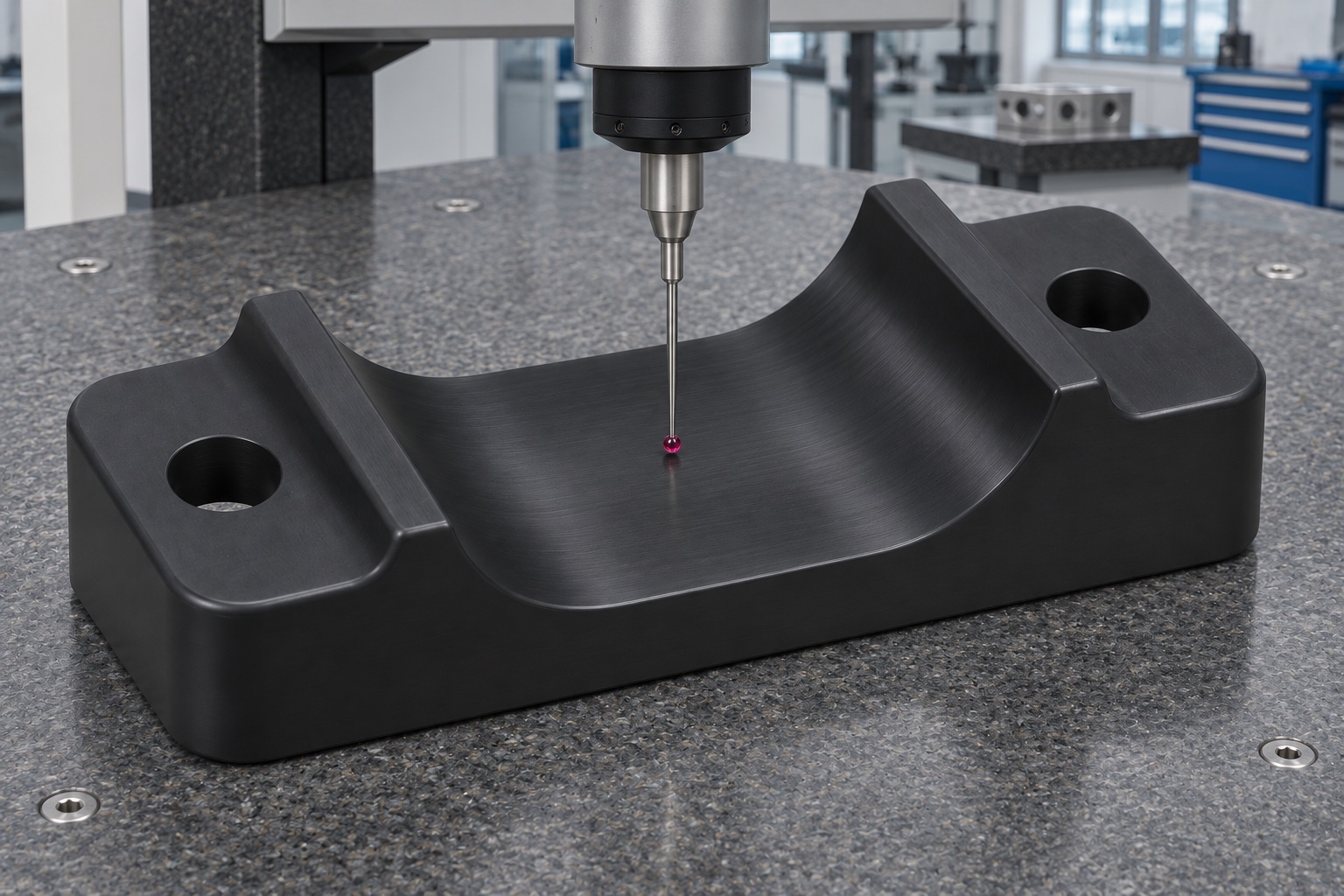
Use only controlled surrogates for fit
Set the saddle on a representative carrier using the specified mounting condition. Insert clean, empty dummy tubes or masters that cover the approved dimensional envelope. Check cap clearance, seated height and access to the separate retainer without forcing the tube into the channel. Where the owner specifies a motion check, use the agreed bench fixture and verify clearance to nearby structures without patient specimens. This verifies selected mechanical interfaces. It does not establish mixing homogeneity, tube retention under service loads, diagnostic accuracy, safety or equipment qualification. Record the master identifiers and configuration for the repeat check.
Trace the cause of poor seating
If a master rocks in the free saddle, look for a ridge, burr or profile error before changing the arc radius. If it sits well off the machine but high in the installed fixture, inspect the mounting face and fastener load. If contact changes only with a particular tube shape, check the approved envelope and label relief instead of widening the cradle for every part. Record the first point of interference and the state in which it appears. Separate evidence about the part from assumptions about the mixer. Refer an unresolved interface conflict back to the design owner before authorizing a geometry change.
Build an RFQ around features and evidence
Provide the drawing, CAD revision, POM-C grade, tube envelope and mounting interface. Identify the required contact band, cap clearance, permitted edge breaks and final measurement condition. Ask for a first-article report for the arc profile, seat height and mounting features rather than a generic statement about tolerances. Clarify whether a dummy tube, retainer or carrier will be supplied for a fit check. Request separate pricing for fixtures, small pilot quantities and repeat low-volume CNC machining. Record any agreed substitutions so repeat orders do not silently change the material or the inspection method.
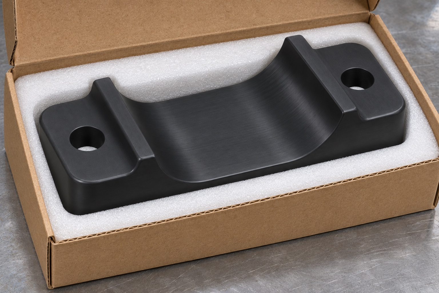
Protect the channel in transit
Support the bottom and wings of each cradle in a dedicated recess. Keep the contact arc free from pressure and prevent hard hardware from entering it. Separate loose screws, masters and mating pieces. Use outer labels or a traveler to connect material lot, part revision and report. Ordinary transit packaging is not a sterile barrier and does not qualify a finished component for a specific handling environment. At receiving, look for chips, pressure marks or distortion before fitting a dummy tube. If the package has shifted, repeat the agreed seat height and visual contact-band checks before accepting the part.
FAQ
Does the saddle retain the tube by itself?
Not in this example. It supports the body. The retainer, carrier and complete assembly must be evaluated separately by the equipment owner.
Why specify height in addition to arc radius?
The radius describes curvature, not the arc's position relative to the mounting face. Seat height depends on both profile and location.
Can one master tube verify every condition?
No. It checks one geometry and setup. Use the approved envelope limits and check cap or label clearances where they matter.
Is an optical end view sufficient for the arc?
Only for the defined section. It may miss a ridge or taper elsewhere along the contact band, so agree additional measurements as needed.
Why measure the saddle after unclamping?
Pressure can temporarily change the shape of the polymer. The released condition helps distinguish machining error from fixture distortion.
Does the fit check verify mixing accuracy?
No. It is a mechanical interface check without patient material. Mixing performance and device validation are outside this component inspection.

tanghangyun@oemach.com