
State the scope of the example
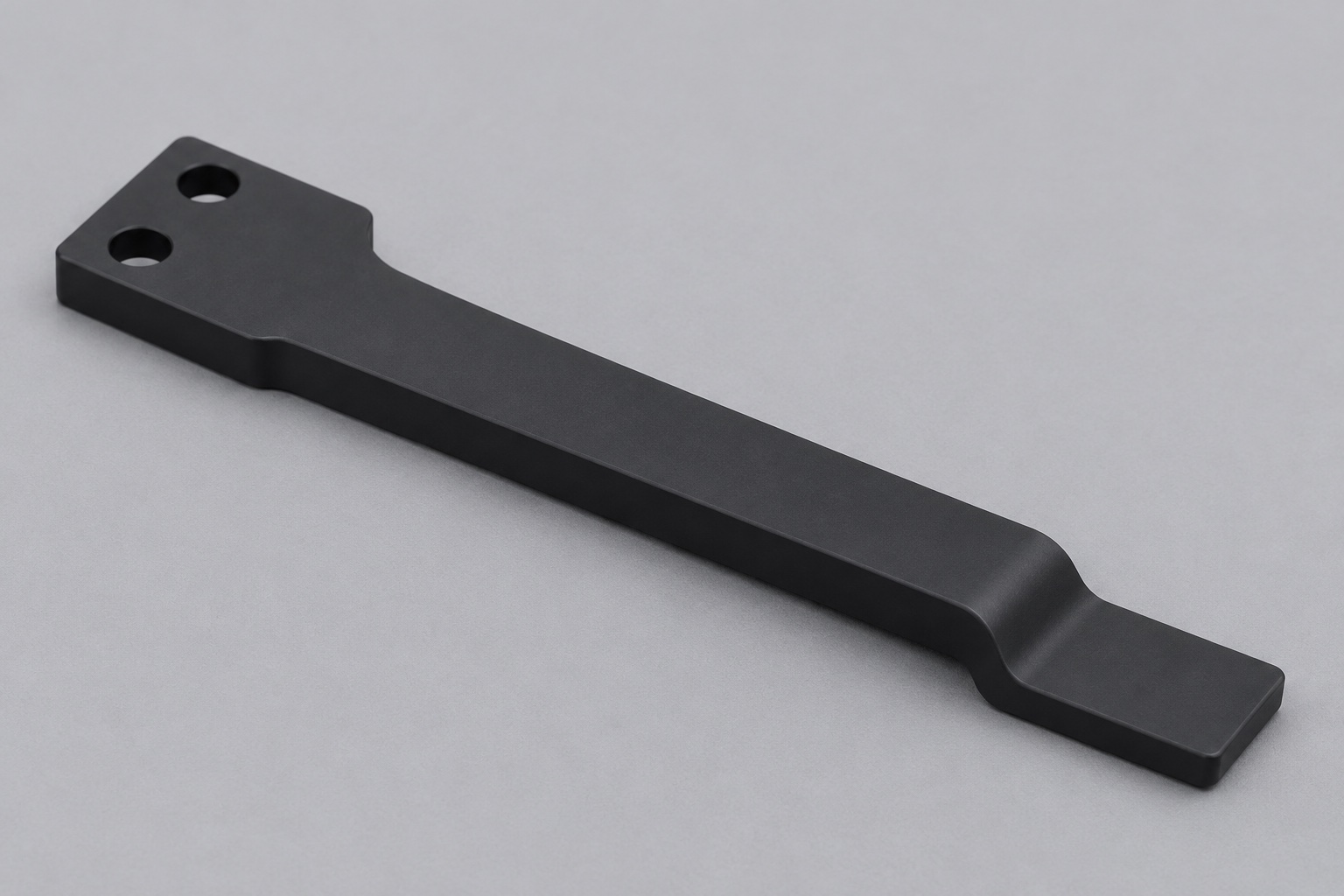
This representative machining case describes a black POM-C acetal escapement finger for a pathology slide loader mechanism. Its wider rear pad has two mounting holes. A narrow shank extends to a short stepped nose with a broad stop face. In a proposed assembly the finger indexes a dummy slide against an agreed edge and clears adjacent guides during release. The example covers a machining route, dimensional inspection and an optional mechanical bench check. It does not describe a shipped customer project, medical certification or measured device results. Material choice and final acceptance remain subject to the released equipment drawing and the owner's requirements.

Agree on the part and assembly inputs
Request the current model and drawing, the rear mounting interface, the allowed slide envelope and the permitted glass contact band. Define which pad face locates the finger and which feature establishes its sideways position. If the mounting holes are just clearance holes, the fixture needs a separate clocking reference. Mark the nose height and the stop face on the inspection view so it is clear where to measure. Include the actuator envelope over its travel and the direction of installation. A supplier can then preserve the features that matter to fit while proposing reasonable methods for surfaces that only provide clearance.
Prepare the stock and track its condition
Select the specified grade and form of POM-C, record the material lot and avoid mixing offcuts with unknown history. Cut a blank wide enough for temporary supporting margins. Identify the seating face and assign a consistent orientation for each pilot piece. A change in stock form or roughing orientation can change how a slender part moves after material removal. Check the blank on supports without pressing it flat, and keep the observations with the setup. If the drawing requires conditioning, define when it takes place and after which operation the part is accepted. Do not assume a generic schedule applies to every grade.
Use a low-distortion first machining setup
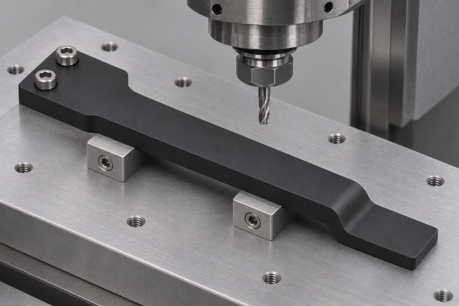
On a three-axis milling center, establish the broad pad face and accessible holes while the blank still has a supporting border. A fixture can locate at the rear and support the shank along its length without pulling the nose into plane. Take balanced cuts where practical and keep chips clear of the workpiece and locating faces. Use sharp tooling sized for the required transition radius. Leave material at the stop face for a defined finish cut. Inspect the pad before moving to the profile operation; a chip or witness mark there can affect every height measurement that references it later.
Finish the profile and release the arm
Locate the blank from the mounting references and finish the stepped nose and shank profile. Keep enough local support to avoid a spring cut at the free end. Separate the final contour pass from the cut that frees the part from its sacrificial stock if the fixture permits. Place any tabs on nonfunctional surfaces and remove them with a defined operation. Handle the nose by supporting the arm, not by using it as a lever. Compare the released part with the setup measurements on the pilot. If the part springs visibly, find the cause before compensating the toolpath or cutting the next lot.
Deburr the mount and contact features separately
Deburr the mounting holes without enlarging their locating surfaces where those surfaces are controlled. At the stepped nose, remove loose strands and inspect the transition under good lighting. Protect the broad contact band from a large manual roundover. A damaged band can shift the effective position of a slide even if a width caliper still reads within tolerance. Use an approved cleaning procedure and prevent chips from lodging at the root of the step. Treat surface marks and cleanliness as separate acceptance requirements. Black POM-C may conceal defects under diffuse light, so view the edge from an angle during the visual check.
Establish repeatable free-state supports
After stabilization, rest the rear pad against the agreed supports without forcing down the nose. If a long shank needs extra support during an optical check, define its position and confirm it does not lift the pad or flatten the arm. Check the pad, mounting holes, narrow shank and nose under the same part identification. Compare at least one repositioning during method development to verify the reading is not a placement artifact. A measurement from a clamped machining fixture is useful for in-process feedback but should not replace the final free-state check unless the drawing defines a restrained acceptance condition.
Record the stop face in profile and height
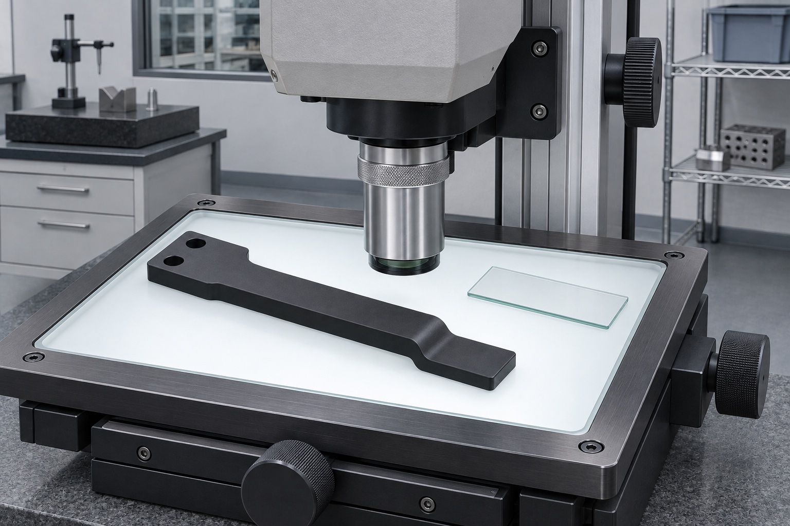
Capture the silhouette of the step and the stop band with calibrated optical equipment under a defined lighting condition. Select the correct focus plane; a strong shadow can be mistaken for an actual edge. Use a separate suitable method to measure nose height from the pad, and include the chosen datum in the report. Verify that any contact method uses low enough force to avoid deflection. Measure the mounting-hole pattern from the specified datums rather than relying on the CAD outline. Record instrument and part condition with the first-article report. No dimensional value is asserted for this representative example.
Screen the assembly with dummy slides
Mount the finger on an agreed coupon or development fixture using the specified hardware. Verify the motion envelope with clean dummy slides at the agreed thickness and edge limits. Check that the nose stops the intended edge and that it can withdraw without rubbing the adjacent guide or disturbing another slide. If installation changes the nose position, inspect mounting contact and fastener load before changing the part. Record which surrogate and fixture revision were used and whether the check concerns clearance only. It does not use patient material or demonstrate the diagnostic accuracy, service life or reliability of a slide scanner.
Define actions for prototype deviations
If the released shank bows, compare material orientation, stock removal and support before cutting the opposite profile. If step height is inconsistent, verify fixture seating and whether the probe moves the part. If profile passes but the nose misses the intended edge, check mounting location and travel before shortening or lengthening the finger. Review each correction against the controlled drawing and record the approved change. For repeat low-volume production, retain the pilot fixture drawing, cutter specification, stock record and inspection method. Do not treat a single prototype fit as evidence of repeat capability or substitute it for the agreed lot acceptance plan.
List clear commercial deliverables
Quote machined components, fixtures and requested inspection separately. Include a material identification record, the required dimensional report, edge criteria and a link between the lot and the drawing revision. If the buyer requests an optical trace, specify the view and the feature it represents. If a fit trial is included, identify who supplies the dummy slides and coupon and who accepts the result. Review what must happen after any supplier or material change. Clear deliverables let engineering compare competing acetal CNC machining routes without guessing whether a price includes a fixture, measurement development or a simple part count.
Protect the slender part in transit
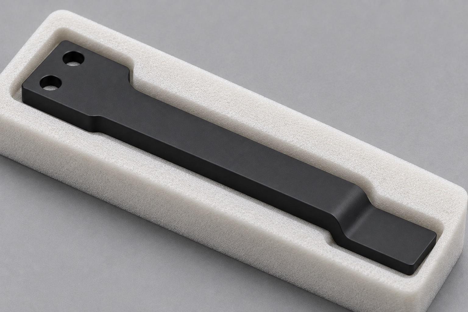
Use one flat pocket per part so the rear pad and shank are supported and the nose is not pressed against a lid or adjacent component. Keep mounting screws or gauges out of the pocket. Link the packaging and inspection record to the part revision, and follow any specified cleaning and handling controls. The tray is for transit protection only, not a sterile barrier. At receiving, inspect the contact edge and the mounting surface under light before fitting the part. If a tray has bent or the parts have shifted, repeat the free-state measurements rather than relying on the previous report alone.
FAQ
Is this an actual pathology scanner delivery?
No. It is a representative manufacturing plan for a slide handling component. It identifies plausible tooling and inspection choices without asserting a customer, certification or test result.
Why use a sacrificial border or support?
Support reduces movement while the narrow shank and nose are being machined. The final inspection is still done after the support is removed in the specified part state.
What is the most useful nose dimension?
The controlled pad-to-stop relationship is often more useful than a nominal overall length. Use the drawing to define nose height, offset and contact profile separately.
How should burrs be removed near the stop?
Remove loose material without rounding back the specified contact band. Inspect the resulting edge visually and check the functional profile if the drawing requires it.
What is needed to quote the fit trial?
Provide the dummy slide envelope, actuator positions and mounting condition, plus the applicable fixture revision. Agree on the intended clearance checks before comparing quotations.
What can a supplier report after a trial?
Report the defined setup, drawing dimensions and observed fit condition if requested. Do not infer device performance or wear life from a short mechanical check.

tanghangyun@oemach.com