
Separate the model support from the scanner's measurement
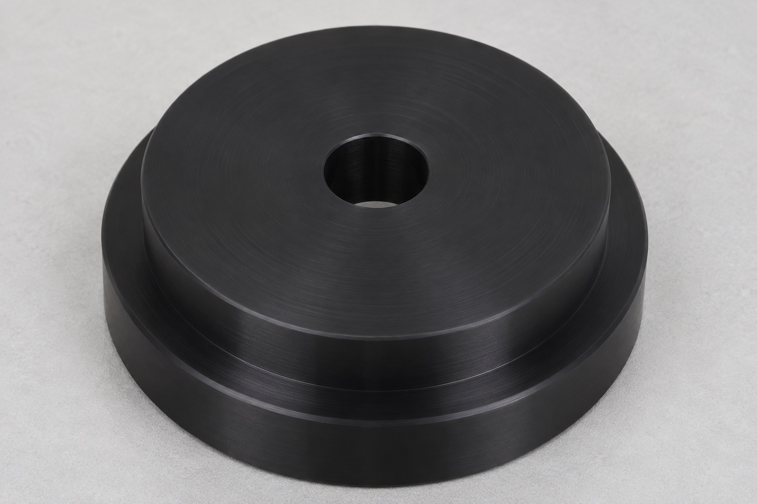
Some dental laboratory scanners hold a model on a support in the scan chamber. In a representative development fixture, a short turned puck provides a repeatable mechanical seating interface for a dummy model carrier. The part is a black POM-C disc with two outside diameters, a flat top and a center through bore. It is not a calibrated artifact, clinical device or replacement for a commercial holder. The mechanical drawing should identify which surface carries the dummy load and which establishes lateral location. Do not infer optical accuracy from the shape or repeatability of one unmarked mechanical part.

Assign the bore, shoulder and face distinct jobs
In the example, a pin locates the center bore and a flat underside rests on a fixture plane. The upper face sets the height of the dummy model carrier. The smaller outside step may simply clear a surrounding feature. If the design instead locates on an outside diameter, specify that explicitly; trying to locate both on a pin and an external step can overconstrain the fit. Identify the active datums and the permitted clearance at the other features. A good section drawing makes it clear what must contact first and what must remain clear when the puck is seated.
Translate insertion into a dimensional requirement
Obtain the limiting pin diameter, tip geometry, usable pin length and intended approach. If the pin shoulder has a radius, confirm that the bore entry can clear it without shortening the effective locating length. An easy fit on a small sample does not show that the puck will accept the largest allowed pin or repeat at the smallest. Establish how much lateral play is acceptable for the fixture's purpose. A snug fit is not an engineering specification. Define tolerances and, if necessary, a separate controlled fit trial with stated references, sample geometry and limits on insertion force.
Plan the turning route around the reference faces
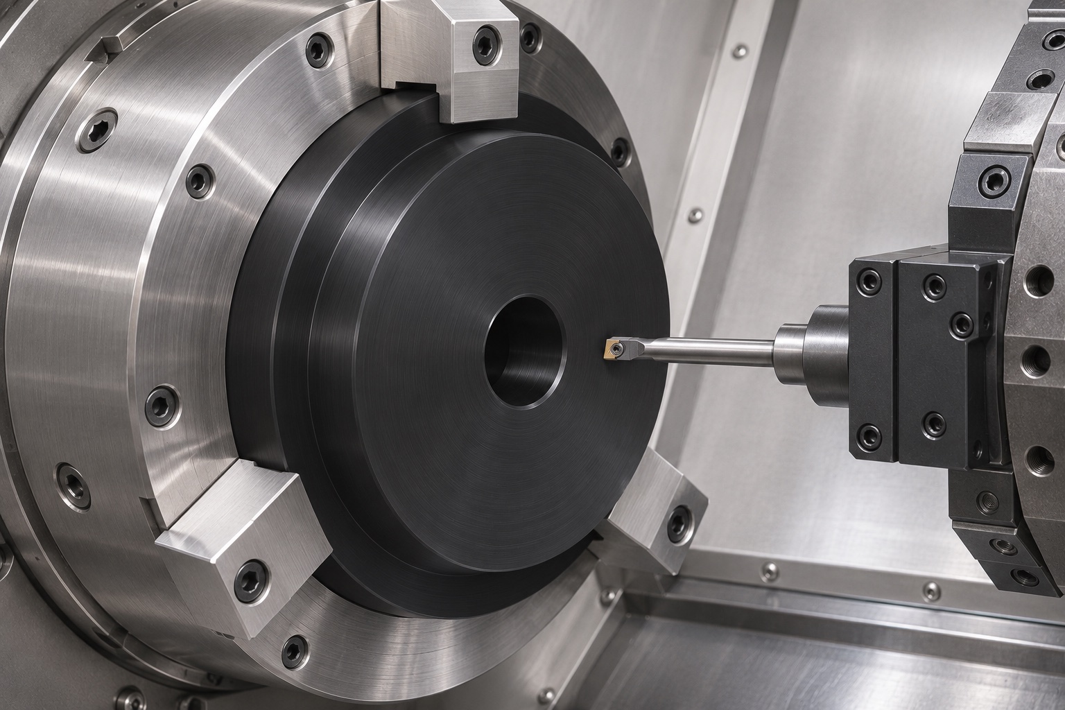
Start with approved round stock, face the first end, then drill and finish the bore. Where the design relates the step and top face to the bore, machining them in one setup can avoid a datum transfer between those features. Leave enough stock for finishing the underside if a second setup is needed. Choose support and clamping that do not deform the disc or mark the finished working faces. After reversing the part, confirm the intended seat rather than touching off an arbitrary exterior. Measure the released part after both operations, especially when the mounting face becomes the primary assembly reference.
Protect the center bore from chips and slivers
Inspect both bore openings after turning and look for a raised lip that can prevent full seating. A generous lead-in may make insertion easier but also reduce the intended contact length. Define an edge break that clears the mating radius without changing the cylindrical locating region. Remove loose material without scraping the bore or rocking a tool against the face. Check any specified flat annular support land separately from cosmetic chamfers. If the part is measured immediately after cutting, make sure chips and temporary heat do not affect a decision about the final condition.
Specify the actual polymer grade and inspection condition
Black appearance does not identify a particular POM-C grade or its additives. Specify stock, condition and traceability at purchase. Support, clamp load and temperature can affect measured dimensions, especially when the part is lightly restrained in a fixture. Agree how the part will be conditioned before final inspection when those effects matter. Do not infer optical absorption, wear life or chemical resistance from the stock name or color. If the scanner design requires particular surface behavior, the equipment owner defines the requirement and evaluates it independently of the mechanical acceptance of the puck.
Verify face height and squareness independently
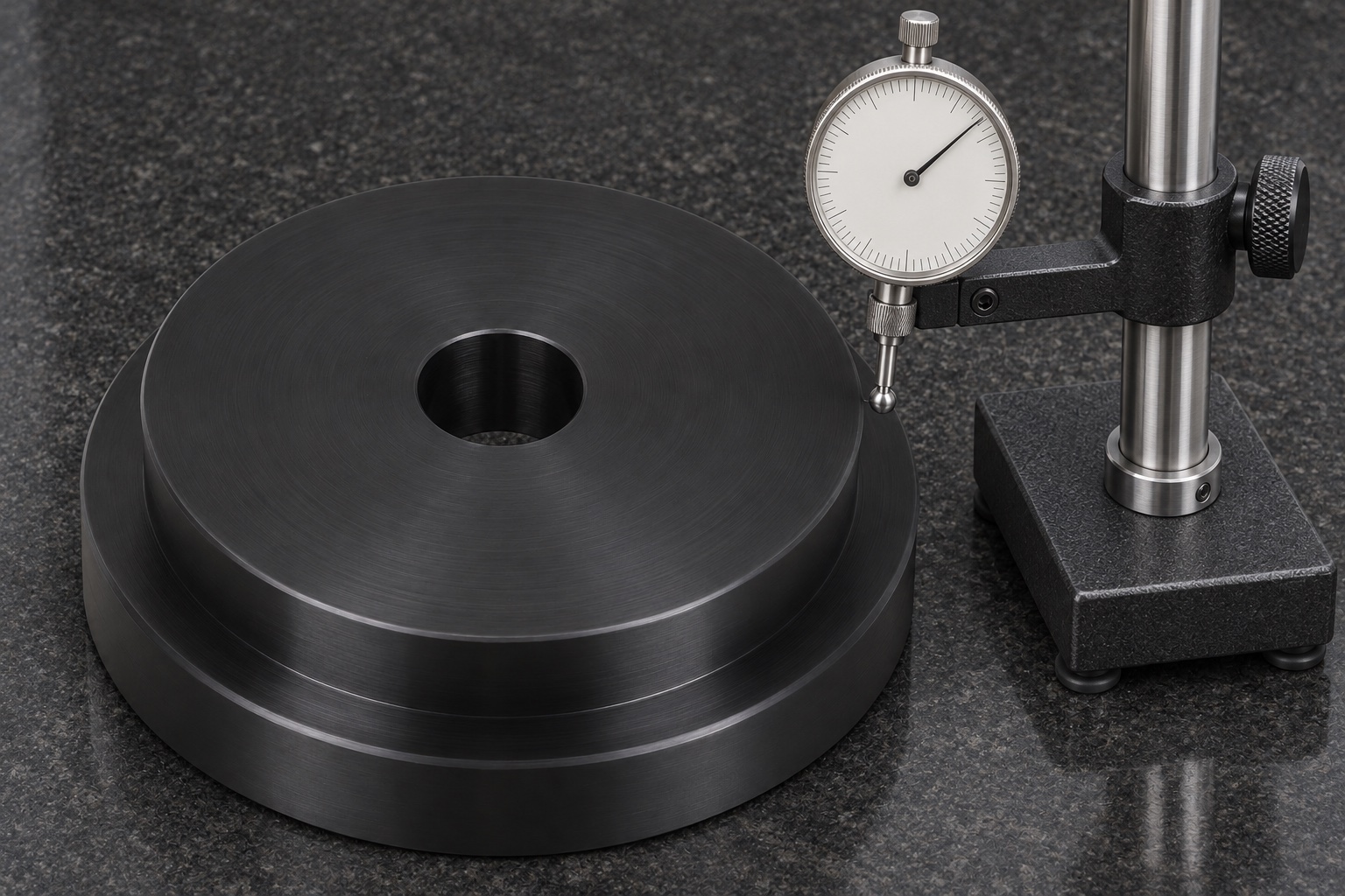
An overall thickness measurement can miss a tilted top face. Set the puck on the specified supports and measure the height at several locations in the actual contact area. If the drawing relates the top face to the pin axis, use a method that establishes that axis rather than assuming the flat plate defines it. Likewise, radial runout of the step relative to the bore is not established by comparing the two nominal diameters. Record which relationship is required, the probe path and support conditions. Use a low enough measuring force to avoid shifting or deforming the part.
Use repeated seating to diagnose variation
A bench fixture can hold a controlled pin and reference plane. Seat the puck, remove it and repeat under the agreed conditions. Observe whether it rocks, binds or changes height, and identify whether the contact occurs at the bore entry, underside or another step. Check the fixture itself for damage and debris. Record the number and conditions of reseatings as defined by the plan. Repeatability on one bench fixture does not establish interchangeability across scanner revisions. It also does not replace measurements of the bore, top face or mating pin if the drawing requires them.
Keep trial results separate from calibration
An inert model carrier or blank fixture can help confirm that the top face supports the intended geometry. Record its drawing and loading condition and keep it distinct from calibrated reference artifacts. A successful trial is evidence about mechanical seating only. Scanner accuracy depends on the actual scanner, optics, motion and evaluation method; those tests remain outside the component order. Do not present black material or a centered bore as proof of improved scans. The equipment owner decides whether a proposed part is appropriate for installation and how the finished scanner configuration must be verified.
Prepare an RFQ for the actual interfaces
Provide the released drawing, model, mating pin and base envelope, quantity and polymer specification. Identify the functional face, bore, locating step and required evidence. Mark any inspection conditions that differ from ordinary shop measurements, including support, temperature and whether the part is inspected free or on an agreed fixture. If a dummy carrier or dedicated gauge is part of the quote, specify its purpose and separate approval. A custom POM-C CNC turning quote is more useful when it distinguishes part geometry from fit testing and optical or equipment-level validation.
Control changes between prototype and repeat lots
Record stock lot, cutting setup, drawing revision and measurement method. Compare the first piece after a tool, stock or fixture change if that change could affect the bore or seating height. If the pin or support revision changes, review the assembly fit before assuming the same puck remains acceptable. Segregate any suspect pieces and use an approved disposition rather than opening a tight bore by hand. Actual measurements and reference conditions help identify whether a difference comes from the part, the fixture or inspection. Do not generalize a prototype trial into long-term process capability without additional evidence.
Pack the faces without loading the center hole
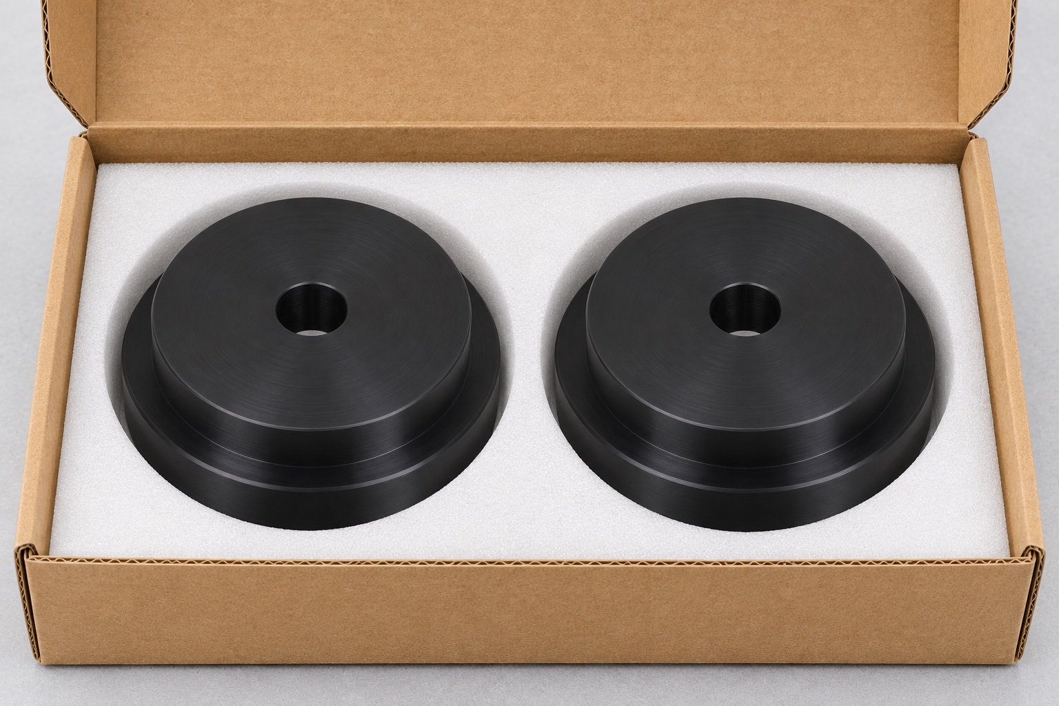
Use individual compartments or a nonabrasive wrap that protects the seating faces and avoids stacking pucks directly against each other. Keep loose filler and tape out of the bore. Mark the drawing revision and lot on the package and retain the link to the inspection record. If special cleanliness is required, define its handling and acceptance separately. Ordinary protective packaging preserves surface condition in transit, not sterility or optical cleanliness. Inspect the puck and fixture at receipt before using them for a fit evaluation; a transit mark can change repeatability even if the part still looks acceptable from above.
FAQ
Is the puck a scanner calibration standard?
No. It is a representative mechanical setup part. The approved calibration artifacts and procedures are separate and must come from the responsible equipment owner.
Which feature should locate the puck laterally?
Use the drawing's defined datum. In this example it is the center bore on a mating pin, not both the bore and an uncontrolled outside step.
Why check more than one point on the top face?
Multiple points can reveal tilt or local high areas that a single thickness reading misses. Use the specified support and sample the actual working region.
Does a large entry chamfer improve repeatability?
Not automatically. It may remove effective locating length. Use the specified edge geometry and verify the fit with the approved pin envelope.
What can a repeat seating trial establish?
It can show how a part seats in the defined bench fixture under the stated conditions. It does not establish scanner accuracy or interchangeability with every configuration.
Is POM-C acceptable for all scanner environments?
No. Specify the exact grade and requirements for the intended environment. Material identity and dimensional conformance do not establish equipment suitability.

tanghangyun@oemach.com