
Separate the bezel from the display module
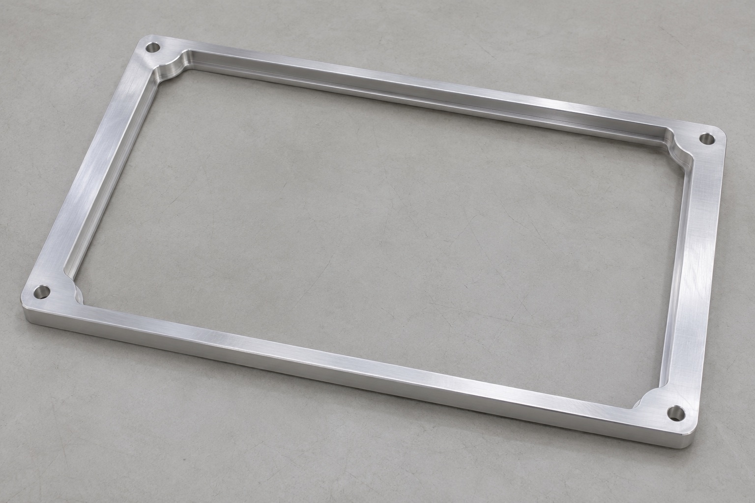
A diagnostic monitor has a display panel and surrounding enclosure. A representative prototype bezel is a slim, open 6061 aluminum frame with an internal ledge and four corner mounting holes. It can locate or clear a mock panel edge, depending on the assembly drawing. It contains no electronics or display glass. The bezel is not a complete monitor, and its dimensions do not establish luminance, diagnostic image quality or an ingress rating. Identify which surfaces meet the housing, which contact an insert and which must leave the active viewing area unobstructed.

Define the visible and mechanical openings
The opening seen from the front may differ from the recess that receives the panel or insert behind it. Use a cross section to show both boundaries, corner radii and any relieved areas. Request the panel's limiting outline and the intended visible area as separate inputs. A front opening can be within its nominal width yet cover a corner if it is shifted relative to the mounting datums. Conversely, a larger rear recess does not ensure sufficient visible opening. The drawing should specify how each profile is located and the depth at which it is inspected.
Control the ledge from the installed references
Identify the rear seating faces and the side or feature that locates the frame on the chassis. Set ledge elevation from those references if the assembly stack depends on it. A measurement from the front face alone can hide a change in overall thickness or rear pad height. Show where the ledge provides support, where it intentionally clears the insert and whether a gasket, tape or compliant layer belongs in the stack. A small raised burr can create a local high point. Do not assume that every part of a visible inner rim is intended to contact the panel.
Support the frame as the central material is removed
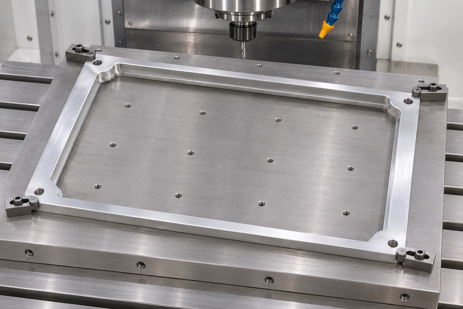
Cutting a large aperture changes the stiffness of the blank. Establish the relevant reference surfaces first and choose supports under the frame, particularly near the corner pads and long sides. Rough the aperture before the final skim where the part is prone to bowing. If the plan uses tabs or a remaining web, document how those features will be removed and where the part will be supported during the last cut. Avoid forcing the part flat solely to make a measurement pass. Reinspect it after release so a fixture-induced flat condition is not mistaken for the delivered shape.
Keep clamping marks off visible and locating surfaces
Place clamps on approved pads or sacrificial material, not on the narrow viewing edge. Verify that no clamp shadows the cutter or blocks access to a mounting hole. Chips beneath an edge support can tilt the frame enough to affect ledge height. Clean and re-seat the first workpiece to test the fixture before changing an offset. Where a temporary setup grips one corner more strongly than the others, look for a twist after unclamping. Define allowable marks on the drawing or inspection plan so the cosmetic standard does not depend on which shift examines the part.
Inspect the hole pattern independently of frame fit
The four corner holes may be clearance features, while side registers or pads actually locate the bezel. Define hole size, position and hardware envelope against the released drawing. Check whether the screws or washers contact the ledge, panel edge or chassis before tightening. Do not assume that a screw entering each hole proves the frame seats without distortion. If the design calls for an installed shape under a specified fastening condition, test it separately from the free-state dimensions. A reviewer should be able to tell whether an assembly problem originates in the hole pattern, the seating faces or the mating chassis.
Make finishing part of the dimensional plan
Specify the 6061 stock condition and whether any anodizing or other finish is required. State which dimensions apply after finishing and the permitted location of masking or fixture marks. A finish can alter clearances where a bezel sits close to an insert or chassis. Compare the required visual condition under agreed lighting instead of relying on an undefined instruction for a uniform appearance. Do not infer cleaning resistance, glare behavior or electrical bonding from an alloy or finish name. Those requirements, when applicable, are specified and evaluated separately by the responsible equipment designer.
Measure flatness, opening and ledge with suitable methods
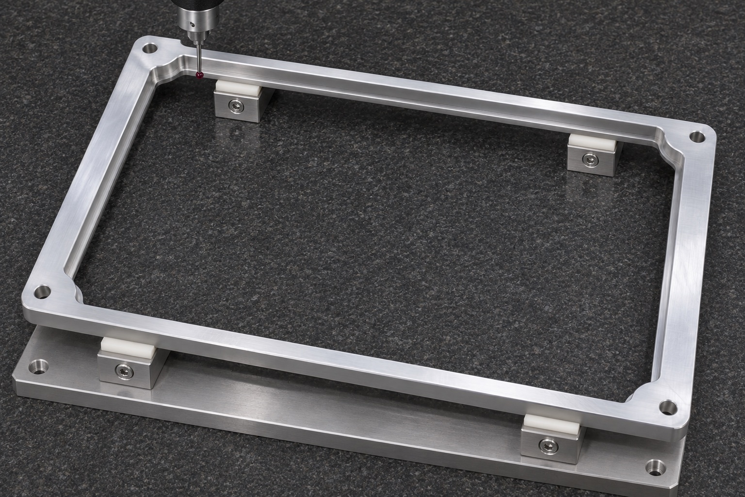
Use the support condition stated on the drawing. For free-state checks, supports should not straighten the frame. Probe or scan the inner contour at the relevant elevations, keeping corner radii and edge breaks distinct from working straight sections. Check ledge height at multiple locations rather than only the middle of one side. The instrument and stylus must reach the shallow step without riding a wall. Record actual readings, drawing revision and support conditions. Use an installed fixture only when it represents a defined assembly condition and keep those measurements distinct from the unconstrained results.
Use an inert panel surrogate for the first fit
An unpowered dummy panel can represent the specified envelope and help identify first contact. Seat the frame against a controlled chassis fixture and record where the dummy approaches the opening, ledge or hardware. Do not apply assembly force to pull a warped frame onto a fragile panel. Describe which envelope and fastening conditions the surrogate represents and which it does not. The trial can reveal mechanical interference or a visible opening obstruction. It cannot demonstrate optical performance, impact resistance, sealing or safe operation of the actual device. Those checks belong to a separate equipment-level plan.
Diagnose variation before editing the program
If ledge heights differ diagonally, check the support and free-state twist before changing depth offsets. If the mock panel catches at a corner, compare both profile radii and locating references before enlarging the entire opening. If the screw pattern is acceptable but the front edge sits unevenly, examine the chassis mating faces and fastening condition. Segregate questionable pieces, document the permitted correction and repeat the affected check. Releasing a small lot based on one manual adjustment makes subsequent orders difficult to reproduce. Keep first-piece data available when stock, tooling or finishing changes.
Quote the actual assembly interfaces
Provide the released frame drawing, model, panel and chassis envelopes, hardware information, quantity, finish and required inspection. Mark the mounting plane, working ledge, visible opening and cosmetic surfaces. State whether a supplier should make a surrogate, supply a dimensional report or verify an installed condition. Identify requirements for packaging or controlled handling separately. A precision CNC milling quote can then distinguish machining from finishing and special inspection. List unresolved requirements before order acceptance, especially when the panel drawing and frame drawing are at different revisions or the allowed mounting force is not specified.
Protect the long sides without using packing as a fixture
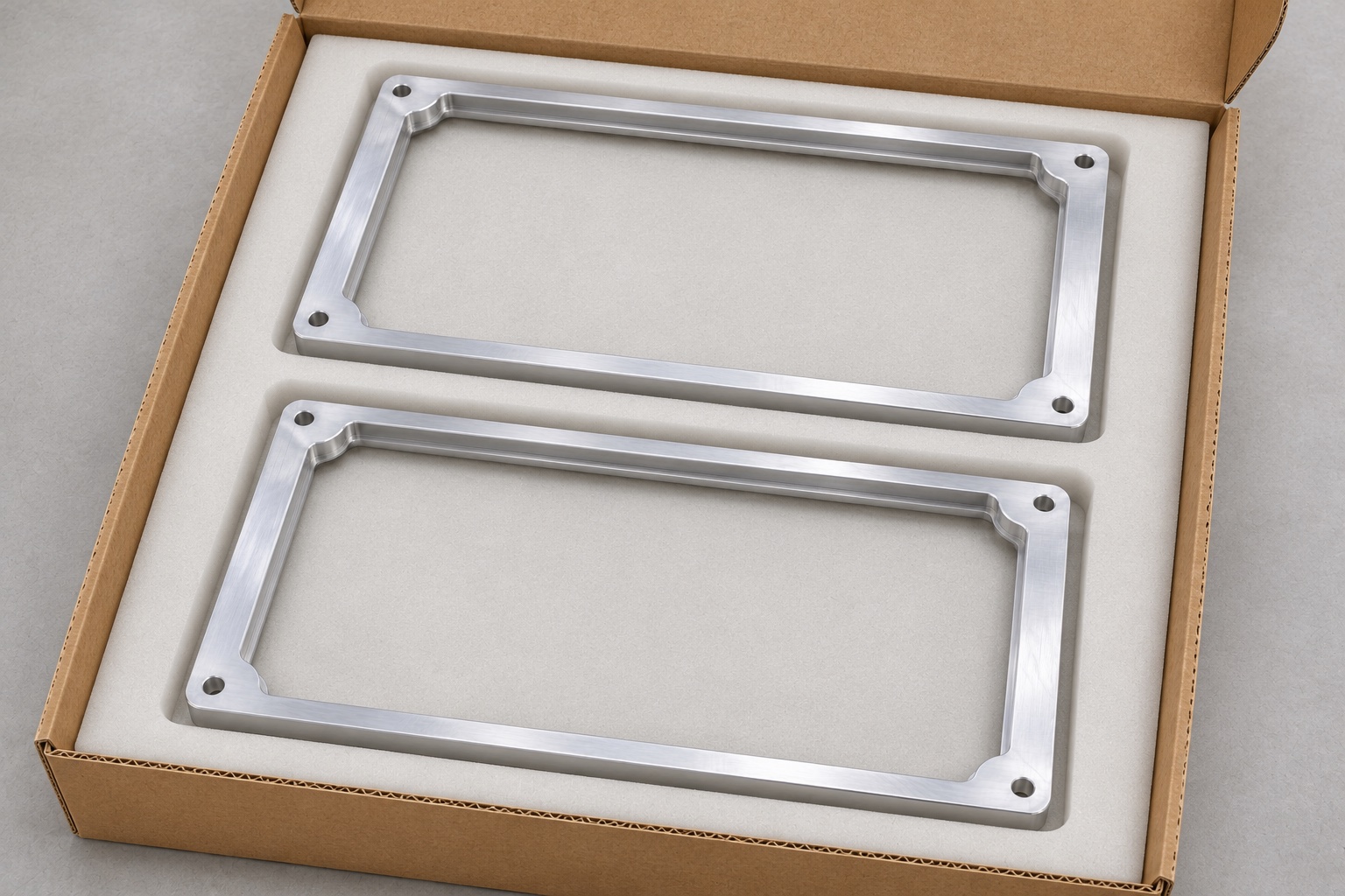
Use individual pockets or straight support with clearance around the viewing edge. Prevent frames from nesting or rubbing the ledge. Avoid tape on visible faces and do not compress the box to straighten the part. Label the package with lot and revision and keep it linked to the inspection evidence. If finish appearance or a defined cleanliness level is required, agree on handling and receipt inspection. This is ordinary protective packaging, not a sterile barrier. Check the frame for transit distortion before using it to evaluate a new assembly interface.
FAQ
Does a machined bezel establish display performance?
No. It is a mechanical enclosure part. Optical behavior, image quality and device-level performance must be evaluated on the approved system.
Why inspect the opening at more than one height?
The front aperture and rear insert recess can have different dimensions and profiles. Measure each where its actual interface occurs.
Can the screws be used to flatten a bowed bezel?
Do not assume so. Follow the drawing's free-state and installed requirements. Pulling the frame flat can load the panel or hide a component defect.
What surfaces should the fixture support?
Use surfaces that reproduce the specified inspection condition without forcing the frame. Record the support positions and fastening condition where applicable.
Is a dummy panel fit enough for release?
Only if the approved plan says it is enough for that particular fit decision. It does not substitute for specified dimensional or equipment-level checks.
What helps prevent damage during shipment?
Support the frame without bending it, isolate the viewing edges and ledge, and keep labels and abrasive packing away from working surfaces.

tanghangyun@oemach.com