
Define the fork as a test fixture component
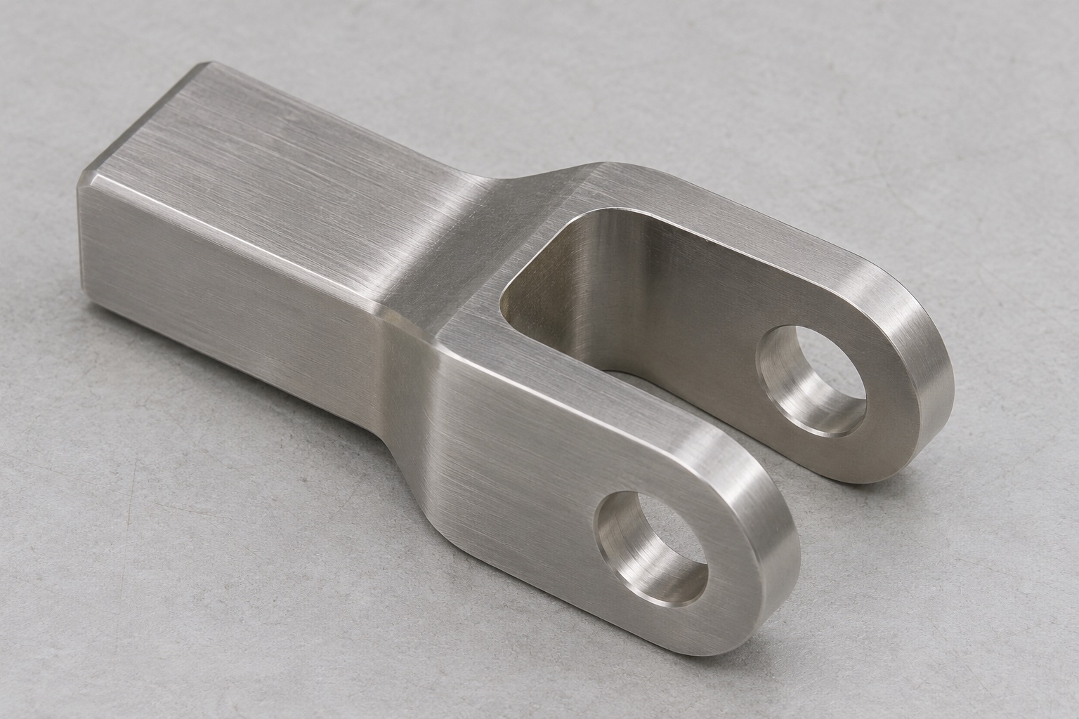
Platelet agitators have moving assemblies. For a separate, unpowered development fixture, a clevis can connect a dummy link to a pin while allowing angular movement. The example is a 316L stainless steel fork with two parallel ears, a rectangular shank and one transverse pin passage through both ears. It is not a replacement for a production agitator component. Write down which surface fixes the shank, how the dummy link is retained and what the fixture is intended to reveal. The scope here is component geometry and unloaded articulation, not equipment qualification or platelet storage performance.

Start with the dummy link and pin
Check the width of the mating link at the pivot, including shoulders, washers or spacers if present. Identify the pin's maximum material envelope, straightness requirement and insertion direction. The bore dimensions and fork gap should be derived from these interfaces and the intended axial clearance. A nominal pin diameter is not enough to determine the whole fit. For example, the pin may pass through both ears yet rub a washer at one rotation angle. Ask for the drawing or a controlled sample of each mating feature before selecting the gap or changing the bore specification.
Establish a consistent datum system
The rectangular shank provides convenient surfaces for a fixture, but the drawing should identify the face and edge that actually locate it. Dimension the bore axis from those references and state how the fork gap is centered or offset. Avoid stacking the bore location from the decorative end contours if they do not set the pin position. If the fixture locates on two surfaces and an end stop, the measurement setup should represent that arrangement. A clear reference system lets the inspector separate incorrect hole position from an inconsistent fork width or a shank that has not seated.
Preserve alignment through the two ears
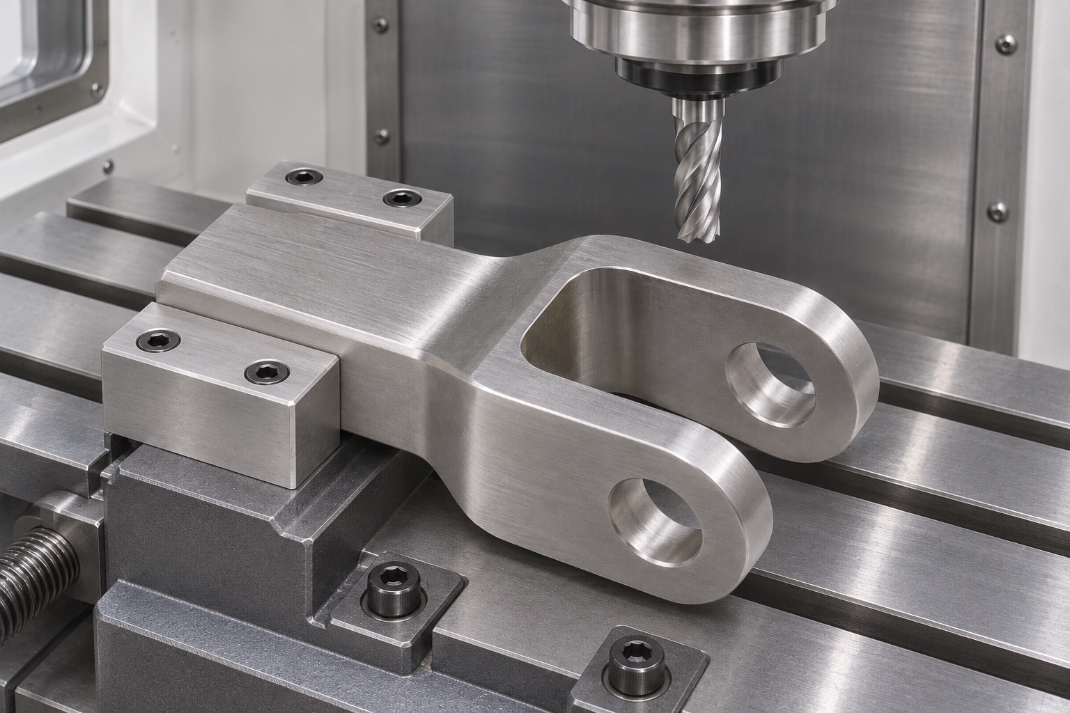
A long drill can wander when it exits the first ear and enters the second. Consider drilling with adequate support and using an appropriate finish method if the drawing requires better alignment or form than the drill can achieve. Where geometry and tooling permit, approach both holes from one direction in a single setup. Validate access, tool reach and clearance in the open gap. If separate setups are necessary, qualify the datum transfer instead of assuming both holes coincide. Check the free-state component after unclamping, since forcing thin ears into parallel during machining can mask actual error.
Treat fork gap as a functional surface pair
Check the gap where the link actually passes, not just at the open tips. The side walls can taper or bow as the fork is released. The floor fillet may also limit how far the link can enter even if its width is within the expected clearance. Identify measuring sections and define any required wall orientation or profile separately from nominal gap. A narrow measuring tool should reach the working faces without touching a radius. Use a fit aid to diagnose interference, but do not replace a drawing-required dimension with a simple trial unless the acceptance plan allows it.
Inspect the internal edges before trial assembly
Deburr the pin entries and the hidden edges where each bore meets the fork gap. The internal exits can retain a lip even when the outer faces look clean. Use an agreed visual method and edge-break limits so the process does not unnecessarily shorten the pin's contact length. Do not force a pin through to scrape away a burr. If a radius is specified where the ears join the shank, verify it independently of the bore edge. An arbitrary hand blend at the root could change the geometry supporting the link and should not be treated as cosmetic cleanup.
Specify the stock and end condition
Identify the 316L material specification, stock condition, required records and any approved finishing. Material identity does not establish corrosion resistance under an unspecified exposure or qualify a component for contact with biological material. For a bench-only fixture, define the actual working environment and any surface care required. Inspect the bore and gap after a treatment where the drawing applies to the finished condition. If a finish contractor needs to grip the part, identify surfaces that must remain free of marks. A material record, finishing record and dimensional acceptance report cover distinct parts of the order.
Distinguish a pass-through pin check from axis measurement
A controlled pin can verify passage through the combined envelope under a stated method. It does not identify which bore is shifted, quantify axis orientation to the shank or report individual hole form. For diagnosis, measure the two bores from the drawing datums and evaluate their specified relationship. If a probe cannot reach the inner edge, verify access with the chosen stylus or use an agreed alternate method. Record instrument, fixture condition and actual readings as required. A pin trial and variable data can complement each other without being treated as interchangeable.
Observe the link through its specified motion
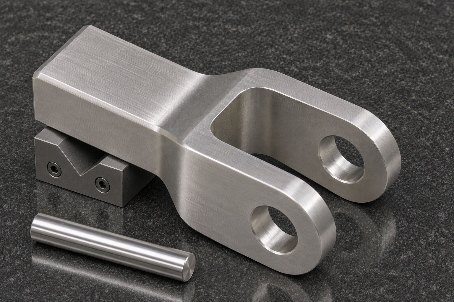
Fit a clean dummy link and approved pin into an unpowered fixture with controlled references. Move the link by hand within the agreed angular span and observe any contact at the ears, root or washers. Record the first point of interference and the sample revisions. Do not run an agitator or use biological material to test an unqualified prototype. A bench observation under no load cannot establish wear, fatigue, pinch-point protection or suitability for service. Any powered testing is a separate decision by the equipment owner with the appropriate design and procedure in place.
Write an actionable first-piece record
Give the drawing revision, stock lot, shank references, bore data and gap readings at the defined sections. Include any required geometry after finishing and report which method was used for the pin passage. Note the unloaded fixture observations separately. If a part binds, distinguish a burr, misplaced bore or wall interference before authorizing corrective work. A repeat order should identify which changes to cutters, fixture or stock trigger a renewed inspection. Keep first-piece observations separate from production capability statements. An example trial describes how evidence would be collected, not how a real lot performed.
Provide mating information in the RFQ
Send the released fork drawing, model, pin and link envelopes, surface specification, lot quantities and required inspection evidence. Identify whether the supplier should quote a trial fixture separately. Clarify whether both internal bore exits must be accessible for inspection and which surfaces may be gripped. A supplier can then choose between a simpler setup and a more controlled alignment process based on actual requirements. Do not request a blanket tight tolerance when only the pin axis or gap limits motion. Make open questions visible before fabrication so that fit is not decided by undocumented rework.
Protect the ears and working bores in transit
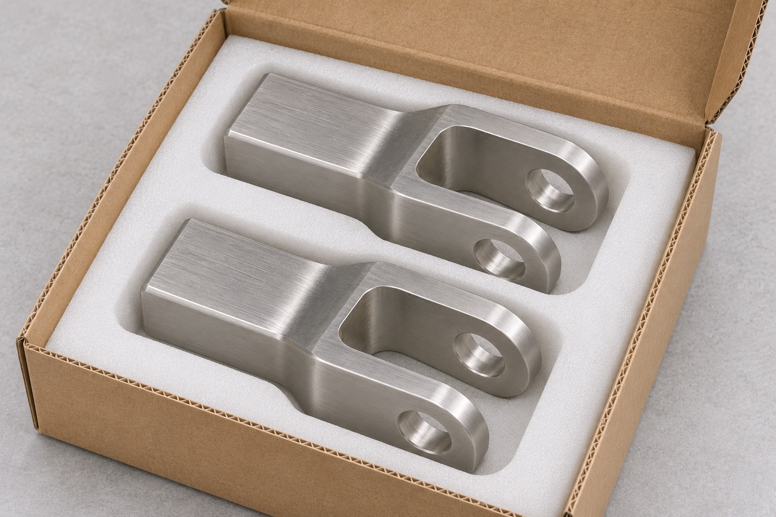
Use individual compartments or a suitable nonabrasive wrap that supports the shank. Avoid packaging pressure on the ear tips and keep loose material out of the fork gap and bore. Identify the drawing revision and lot on the package, and link the label to the dimensional evidence. If a pin or reference link travels with the parts, package it separately to prevent contact damage. Ordinary protective packaging is not a sterile barrier or a controlled cleanliness claim. Agree on any special receipt condition separately and check parts for damage before putting them into the bench fixture.
FAQ
Can a clevis from this example be installed on an agitator?
No. It is a representative component for an unpowered bench fixture. A device modification or replacement requires separate authorization and validation by the responsible equipment owner.
Why measure both ears instead of only trying a pin?
A passing pin checks a combined envelope. Measuring both bores can locate the cause of misalignment and evaluate their relation to the mounting references.
Where should the fork gap be checked?
Use the drawing's working sections, away from entry chamfers and root radii unless those features are specifically being evaluated. Check more than one depth where taper matters.
Does machining both bores in one setup ensure alignment?
It can reduce setup differences, but tool deflection and workholding can still affect alignment. Confirm the released geometry using the agreed method.
Does a hand articulation trial establish wear life?
No. It shows only the behavior of the specified fixture and samples under the trial conditions. Loads, fatigue and service life require separate evidence.
What should packaging protect first?
Protect the ear tips, bore entries and working gap from impacts and debris. Support the shank and maintain the link between package identity and inspection records.

tanghangyun@oemach.com