
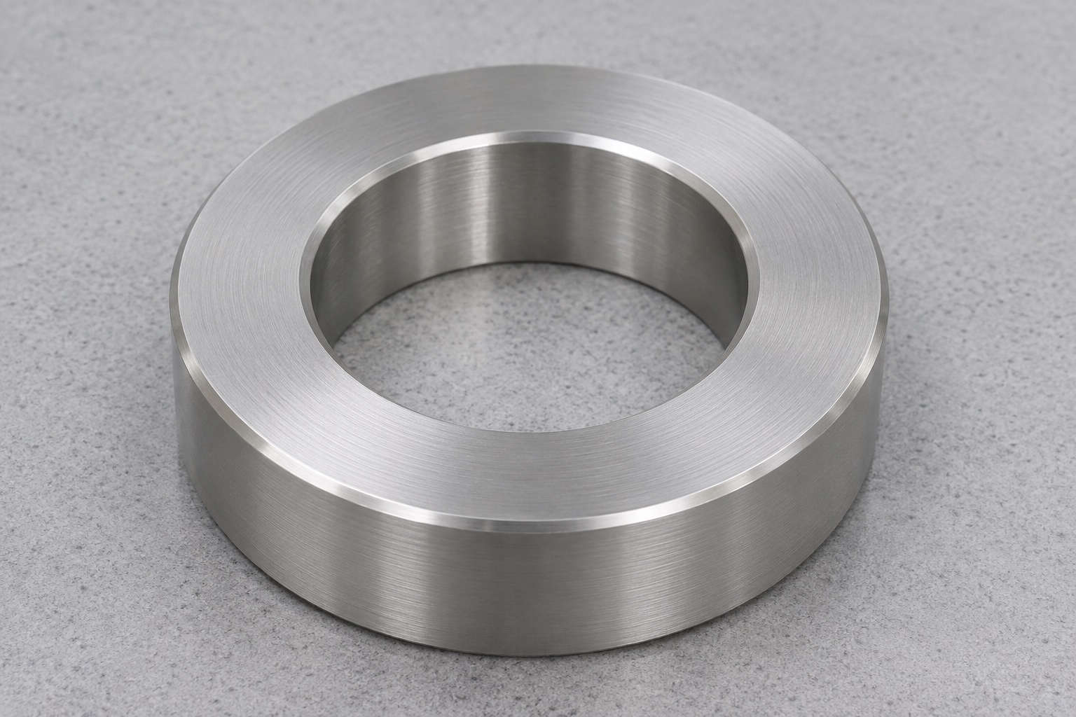
Define the ring as an inspection tool
A removable handle is one mechanical interface on some surgical lights. For a drawing-controlled handle design, a shop can use an inspection ring to check whether a specified cylindrical section can enter a defined bore. The example is a plain 316L stainless steel ring with flat annular faces and a small entry chamfer. It is a bench tool, not part of the light and not a clinical accessory. State the exact handle section, approach direction and depth checked. An acceptance decision for that envelope cannot establish retention, load capacity, sterilization compatibility or safe use of the complete equipment.

Start from the handle drawing, not a convenient sample
Obtain the released handle drawing and identify the external envelope at the working section. A smooth handle can still have ribs, keys, a taper or an axial step outside the region intended to pass. Decide whether the ring checks a single cylindrical segment or whether another tool is needed for noncircular features. A sample can help clarify insertion geometry but should not silently define limits. If the handle drawing changes, review the ring before using it again. The gauge record should identify the drawing revision and the range of features covered, not just a part name.
Specify what a pass means
Document the prescribed insertion direction, depth, handling condition and allowed force. If it is a go check, passing indicates the handle enters the ring under that method. It is not a numerical size measurement, and it does not verify a minimum external diameter. If another limit or a separate dimensional report is needed, define it on the inspection plan rather than interpreting one go ring as two checks. Consider gauge tolerance, wear policy and measurement uncertainty when selecting the bore limit. The party responsible for acceptance should approve the gauge design and decision rule before a machining order is released.
Machine the bore with a stable datum
The ring can start as suitable round stock or a preformed blank, provided material identity and cleanup allowance are maintained. Face the first working surface and rough the bore, then finish it with suitable tool reach and support. Where the drawing relates the bore to a face, finish both in the same setup when practical. Clamping pressure can temporarily change bore shape, particularly as wall thickness decreases. Check the geometry after release and again after any required finishing. If a second setup is needed for thickness or the rear face, use support that protects the finished bore and annular seating surface.

Control the entry independently of the measuring zone
A small entry chamfer helps align the handle and protects the edge. It should not extend into the cylindrical region used to make the acceptance decision. Show the chamfer limit, working bore length and intended insertion depth separately on the drawing. An enlarged lead-in can allow a handle to appear to enter even though it never reaches the controlling surface. Check both ends for burrs and inspect the transition without rounding it by hand. If the ring can be used from either face, the inspection plan should account for both entries rather than relying on a visual assumption of symmetry.
Choose an alloy and finish without assuming gauge life
316L is one possible material for a protected bench ring. Specify stock identity, surface condition and any finishing operation separately. For repeated contact, consider wear, surface damage and the possibility of material transfer from the tested part. The responsible metrology owner decides whether the material and process are appropriate for the intended duty. Do not assume that a stainless ring has an unlimited useful life or a particular hardness. Where dimensional limits apply after a finish, verify the final bore and faces. A documented material grade does not replace inspection of the working surfaces or control of the gauge in use.
Measure bore size and form as separate characteristics
Use an internal instrument suitable for the target tolerance and ring size, with the appropriate reference standard. Read at specified depths and angular locations away from the chamfer. Compare the measurements to identify taper or possible ovality, then use a dedicated form method if the drawing requires a form result. One diameter measurement cannot demonstrate the entire envelope. Record temperature, support and instrument uncertainty when relevant. If the chosen method cannot resolve the decision limit, qualify a better measurement route or send the ring for external verification. Do not make an acceptance claim based on a device that only displays more digits.
Keep the gauge decision independent of the reference check
Use appropriate reference masters or an approved measurement route to verify the ring. A production handle cannot by itself prove the gauge has the correct bore. When trialing the method, compare the behavior of the reference with the expected fit and document the procedure. A known master can support an ongoing condition check, but the periodic verification plan should specify the required measured characteristics and intervals. Keep the ring identifier, drawing revision and verification status visible on its container. If direct marking is required, use a drawing-approved location that cannot affect the working face or bore.
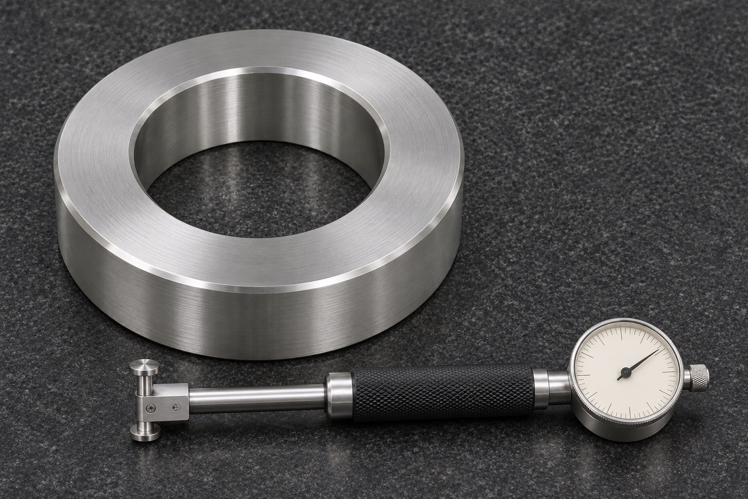
Deal with marginal decisions consistently
When a handle stops before the intended depth, inspect cleanliness, orientation and the contact region before forcing a decision. Record whether the issue is at the entry, in the working bore or outside the gauge's defined span. Do not apply extra force to obtain a pass. Use the approved escalation method for ambiguous results, such as another dimensional method or a verified replacement gauge. A part should not be accepted solely because it passes in one uncontrolled orientation. Record the disposition and retain the link to the gauge that was used, especially if the gauge is later found to be worn or damaged.
Include inspection evidence in the order
A quote for a custom surgical light handle inspection ring should state the gauge drawing, bore geometry, measurement requirements and intended handling. Specify whether the supplier is providing a machined ring, a dimensionally verified gauge or a gauge with additional calibration documentation. Those are different deliverables. Identify any reference master, marking and protective storage requirements. Separate the ring dimensions from the workpiece dimensions so the two limits cannot be confused. If the gauge will be used on an inspection line, include the condition checks and escalation process expected at handoff rather than leaving them to informal shop practice.
Protect the working bore between uses
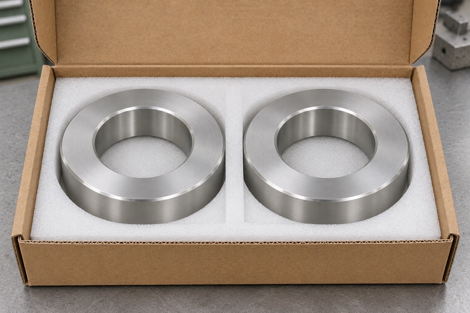
Keep the ring in a dedicated pocket, away from loose tools and other rings. Avoid inserting abrasive material into the bore during packing. If the ring is handled frequently, define a suitable care method and withdrawal criteria for a nick, corrosion or unexplained measurement shift. Where a cover is used, make sure it does not rub the measurement surface. Identify the gauge on its container and preserve the link to its verification record. Ordinary protective packaging is not sterile packaging. The ring belongs in the designated inspection area and should not be installed on equipment or used as a clinical tool.
Review wear before approving a new lot
A ring can change after a drop, repeated use or unauthorized polishing. Verify it at the agreed interval and after events likely to affect the bore. If it is outside limits, quarantine it and review decisions made since the last acceptable check according to the quality plan. Do not reclassify a worn ring as an acceptable gauge without a documented decision. For repeat orders, confirm that the same workpiece drawing and gauge decision rule still apply. A new ring with a familiar shape is not interchangeable unless its identity, limits and verification evidence support that conclusion.
FAQ
Does a pass in the ring verify the handle lock?
No. It addresses a defined external envelope. Locking, strength and reprocessing require separate checks of the actual equipment and configuration.
Can one bore check verify both handle size limits?
Not with a single go ring. Define the complementary limit or variable measurement method separately if the inspection plan requires it.
Why control the entry chamfer?
It aligns the workpiece but does not serve as the measuring cylinder. Excessive relief can shorten the effective contact length or give a misleading partial entry.
Is a production handle an acceptable calibration master?
Not by default. Use the approved reference standard or measurement method. A production sample is not a master merely because it fits.
Can the gauge be polished if it feels rough?
Not without approval. Polishing can change the working bore or edge. Withdraw the ring and verify it against the documented criteria.
What should accompany the ring at receipt?
The drawing revision, gauge identity, material record if requested, measured geometry and any contracted verification or calibration documentation.

tanghangyun@oemach.com