
Separate the carrier from the scale and its reference
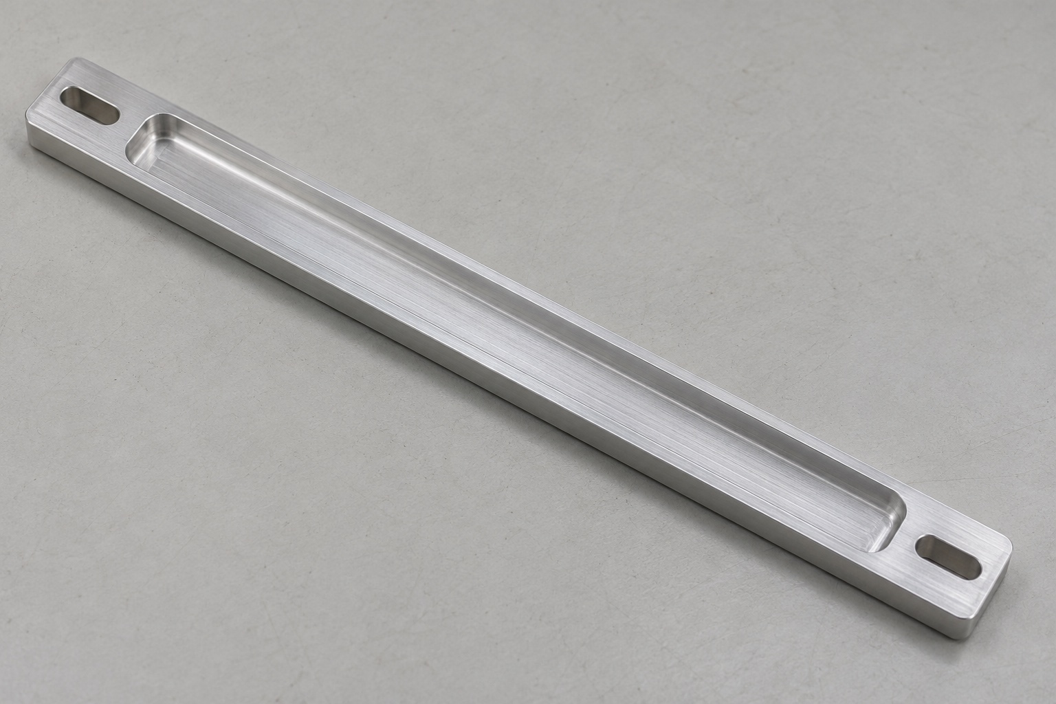
A slit lamp headrest may have a height reference. In this example a narrow aluminum carrier supports a separate reference strip on an upright. Its long shallow pocket positions the strip, and two oblong holes permit assembly adjustment. The carrier is not itself a graduated scale, a calibration device or a patient support. A useful drawing says which mechanical surfaces seat the strip and how the assembly establishes the height reference. A part can meet every dimensional callout without establishing that the installed mark has the intended relationship to the optical system.

Decide how the strip locates in the recess
Identify whether the strip sits against one long side, bottoms against an end or floats until an alignment step. Show the usable support area and corner relief separately from the overall pocket size. If an adhesive or liner occupies space under the strip, include its allowed thickness in the stack. A narrow strip can bridge a high spot in the floor and lift elsewhere. Where support is important, specify the floor profile or flatness and the areas that may remain relieved. Request the strip's limiting outline rather than designing from a nominal rectangular sketch alone.
Define adjustment travel using actual hardware
The two end slots have width, end radii, length and relative position requirements. Their useful travel also depends on the diameter and alignment of the fasteners. Include the intended washer or screw head envelope so it can be checked against nearby edges and the strip. If the slots allow movement along the upright, define how unwanted lateral rotation is controlled during assembly. Avoid using slot length alone as a promise of installed range. A fixture can verify available movement with the specified hardware, but the full instrument may add constraints that the bench fixture does not represent.
Plan machining support for a long narrow blank
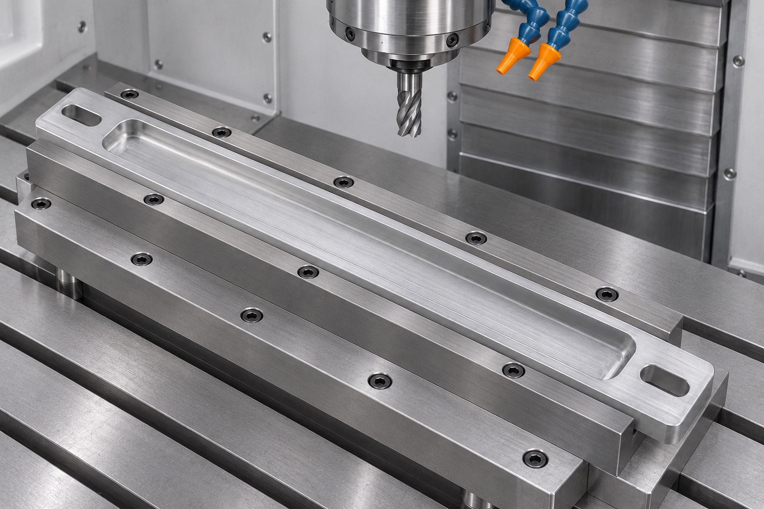
Use a fixture that supports the stock along its length and leaves the pocket and end slots accessible. Establish the rear mounting face and the long side used for reference before cutting features that remove stiffness. Rough the pocket with a controlled allowance, then verify the condition before finishing if the blank is prone to moving. Avoid pressing a bowed strip flat and treating the clamped dimension as the released geometry. Mark the intended free-state inspection supports on the plan. A short unsupported span near a slot may need a backing or another setup to control edge damage.
Keep the pocket depth tied to strip height
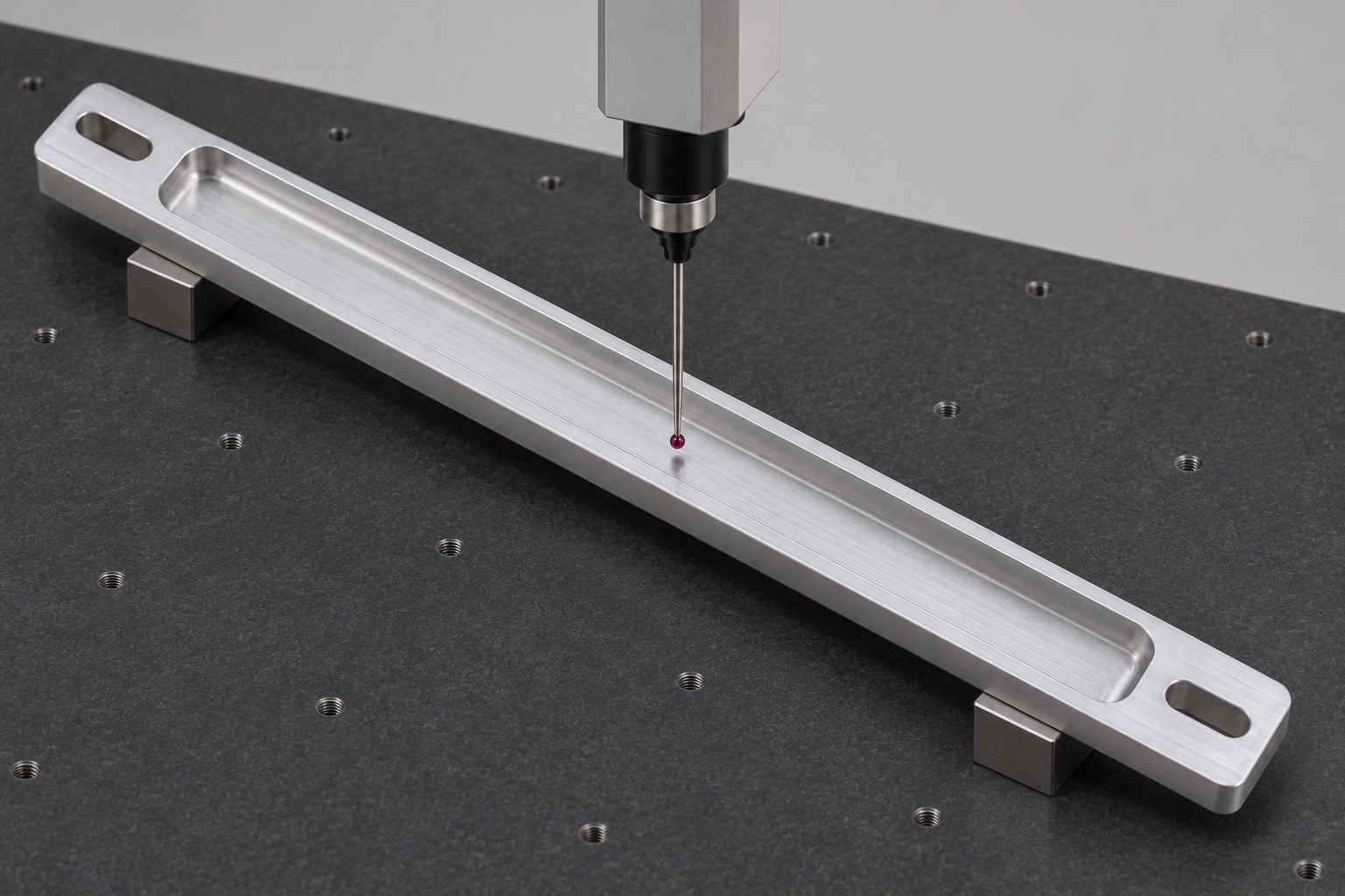
The floor depth from the top surface describes one relationship, while the height from the mounting face to the floor describes another. If strip projection matters relative to the upright, include the full stack with plate thickness, strip thickness and any attachment layer. Use a measurement plan that reaches the actual contact region rather than probing a corner radius. Take readings at multiple locations along the length where the strip bears. A single middle reading can miss a tapered floor or bowed base, particularly when the fixture flattens the part during the cut.
Protect seating surfaces while breaking edges
Deburr both faces of the end slots so the fastener and washer can seat and the rear face can contact its support. At the pocket, avoid aggressive blending that reduces a locating wall or removes material from the supporting land. Define edge breaks near the strip and fasteners explicitly when the general note is not sufficient. Use agreed visual criteria for any surface the operator will see. Inspect for embedded chips and raised edges before trial assembly. A cosmetic polish cannot compensate for a pocket or slot that no longer meets the drawing after hand finishing.
Treat anodizing and appearance as separate specifications
State the 6061 stock condition, required finish and whether each critical dimension applies before or after finishing. If anodizing is specified, identify any masked areas or acceptable fixture marks. Verify clearance where a coating can affect the pocket, slots or mounting surface. Do not assume that a particular alloy or color ensures durability under an unspecified cleaning procedure. If the design calls for resistance to wear, cleaning or lighting conditions, the equipment owner defines the applicable tests. Machining acceptance can cover the dimensions and agreed finish without asserting performance of the finished ophthalmic instrument.
Measure the plate in the specified support condition
For a free-state flatness check, use the agreed support points, orientation and method. A mounting check may instead use a controlled straight reference and the designated hardware. Keep those results distinct. Use a coordinate measurement system, depth measurement or suitable optical method according to the feature and uncertainty needed. Check the recess at accessible locations and measure the oblong slots away from chamfers. Document which side is the mounting face and how longitudinal position is established. A part placed on an uneven fixture can show apparent twist unrelated to the machining process.
Test a blank strip and hardware before final assembly
A controlled unmarked strip can help assess insertion, seating and any protrusion above the carrier. With the intended hardware and a mock upright, check the allowed sliding range and whether the strip interferes with the heads. Define the trial condition and record the strip and fixture revisions. This can identify assembly issues without using marked production parts. It cannot prove height-reference accuracy or patient positioning performance. The equipment manufacturer must verify the scale, installed alignment and finished system using the approved method. Do not release a substitute component for a named instrument based on a bench fit.
Make a small-batch first-piece plan
Agree on which measurements are taken after milling, after any finish and at final inspection. Record material identity, drawing revision, fixture and measurement setup. If a long part curves after finishing, compare the free-state condition at the earlier stage before changing the drawing. Decide which changes to cutter, stock, clamping or finish require a renewed first-piece check. A short lot can be inspected feature by feature when necessary, but any sampling choice should be agreed rather than implied by a stock phrase. Keep fit-trial observations apart from dimensional measurements and finish records.
Include mating information in the RFQ
Provide the drawing, model, rear interface, strip envelope, hardware and adjustment direction. Specify the required quantity, material, finish, inspection documentation and packaging. Mark which characteristics the machinist is expected to control and which belong to the assembled system. Ask the supplier to identify any necessary fixture or special depth measurement and any unresolved requirements. This makes a custom precision CNC milling quote more useful than a price for a generic slotted bar. If engraving or scale installation is separately required, give its own drawing and acceptance criteria rather than assuming it is included.
Protect a long carrier from bending and scuffing
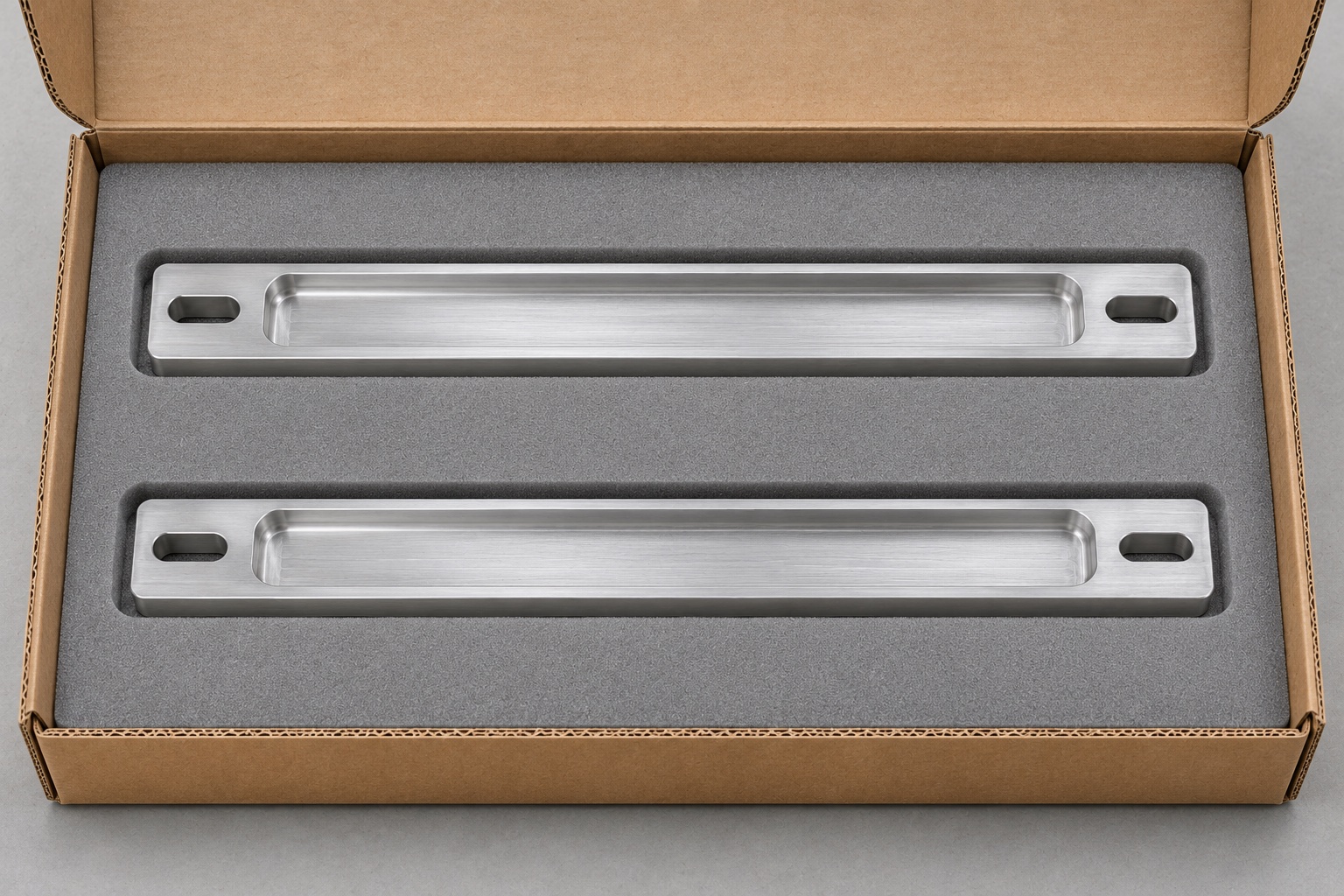
Use a straight protective insert or divided tray that supports the plate along its length and isolates adjacent parts. Avoid loading the long pocket with packing pressure or placing adhesive on the mounting face. Put part identification, revision and lot on the outer packaging. If finish appearance is critical, agree on the wrapping contact areas and inspection condition at receipt. Do not use the pack as a fixture to bend a part into specification. This is ordinary protective packaging; controlled cleanliness or sterile packaging would require separately defined handling and validation.
FAQ
Is the carrier a calibrated measuring scale?
No. It is the mechanical mounting plate for a separate strip. The equipment owner defines how the strip is marked, installed and verified in the finished system.
Why use slots instead of round holes?
Slots can allow adjustment along a defined direction. The usable range depends on slot geometry, hardware and other assembly constraints, so specify and verify the actual interface.
Should pocket depth be checked from the top or the back?
Use the drawing reference. Depth from the top helps control strip projection, while height from the rear face helps control the installed position. Some designs require both relationships.
What causes a narrow plate to bow after milling?
Stock condition, material removal, support and clamping can all contribute. Compare the part before and after releasing the fixture and review the process before adjusting offsets.
Does a blank strip fit prove the height reference is correct?
No. It checks the physical fit under the specified conditions. Mark position and system alignment are separate installation or qualification checks.
What documents help repeat the machining order?
Provide the current drawing, strip and upright interface revisions, required finish, dimensional records and inspection support condition. Identify any changes requiring renewed first-piece approval.

tanghangyun@oemach.com