
Define the mount as a mechanical interface
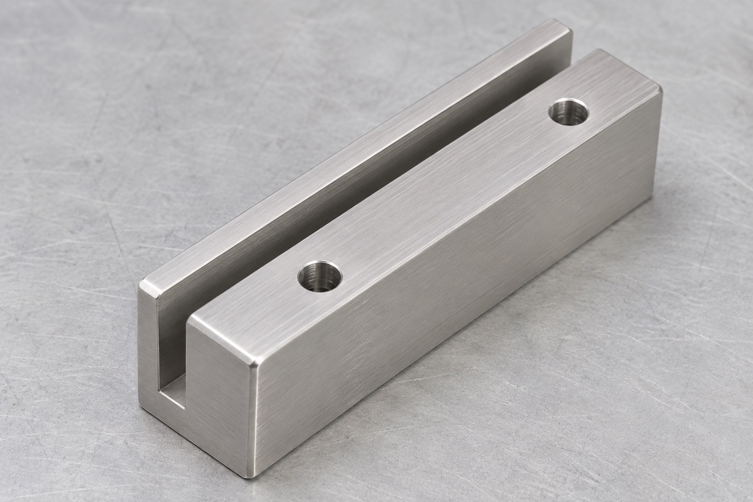
Some pathology grossing workstations use shields as accessories. A representative edge mount can be machined as a short block with a straight open-ended slot and two vertical mounting holes along the wider side. The slot receives the lower edge of a drawing-controlled panel or edge insert. The holes attach the block to the workstation, not to the panel. The part is one element of an assembly, not a complete shield or retention system. A suitable machining specification distinguishes the surfaces that position the panel from the features that fix the block to the support.

Establish the panel envelope before setting slot limits
Use the minimum and maximum panel edge dimensions, including any liner, edge protection or finish that occupies the channel. A sheet measured in the middle may differ from its edge if that edge is rounded, tapered or wrapped. Confirm how far the panel enters and whether it rests on the floor, on a pad or at another stop. Determine whether the block is intended for sliding installation or static placement. A drawing that calls out only nominal slot width leaves those questions unresolved. The design owner defines the permissible movement and the features that retain the panel.
Reference the slot from the installed base
The underside of the block can establish how the channel sits relative to the workstation. Use the real mating face as the primary reference, then establish the lateral position and end reference as the drawing requires. Dimension the slot location and its height above the base separately from the overall block thickness. If a broad exterior surface does not locate the part, do not use it as a substitute datum without agreement. An apparently centered channel can still sit at the wrong height relative to another block if the mounting and machining references are inconsistent.
Plan the cut around wall stiffness
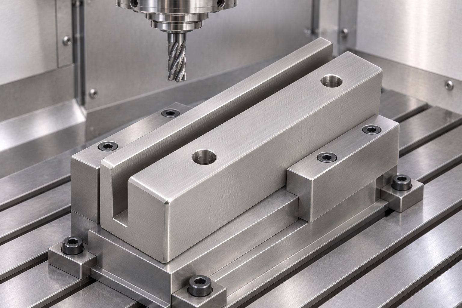
Support the blank on clean, stable surfaces. Establish the base and a side reference first, then rough the channel with room for a controlled finish pass. Consider the changing stiffness of the two cheeks as stock is removed. Gripping the thin cheek after slotting may temporarily narrow the channel or mark its outer face. Keep clamping pressure on supported stock where practical, and verify the part after it is released. On a prototype, use the first cut to confirm chip evacuation and tool reach before committing to a full lot. A worn cutter can leave a burr and a size error at the same time.
Separate slot width, taper and floor condition
A pin or rectangular gauge may enter at one end yet bind near the center. Measure width at locations and depths that represent the working portion of the panel edge, away from entrance chamfers. If the floor supports the panel, specify its depth from the relevant mounting reference and check that debris or an unintended radius does not prevent seating. If the floor is deliberately relieved, evaluate the shoulders that actually provide support instead. Define the straightness or profile requirements where a long mating edge makes them important. Avoid assuming that one width value describes the complete channel.
Protect the panel from the machined edges
The mouth needs an entry shape that does not catch the panel or its liner. Use a controlled chamfer or radius where the drawing permits it, and distinguish it from the channel width that remains below the lead-in. Inspect open ends, the base of each wall and the underside of the mounting holes for burrs. A raised edge under the block can affect seating even when the channel looks clean. Check the opening with suitable light and magnification, if required. Do not polish away a defined contact surface to eliminate a cosmetic mark.
Specify alloy and surface requirements separately
Request the 316L stock designation, condition and traceability appropriate for the order. Identify the intended finish and the surfaces it applies to. If the design specifies a treatment after machining, define the acceptable condition and the evidence required from that operation. The alloy alone does not establish compatibility with an exposure or cleaning procedure. Do not infer chemical resistance, cleaning efficacy or sterility from the appearance of a stainless part. Dimensional acceptance after finishing and suitability in the installed environment are distinct questions, and the responsible equipment owner specifies the latter.
Inspect the mounted geometry without hiding free-state variation
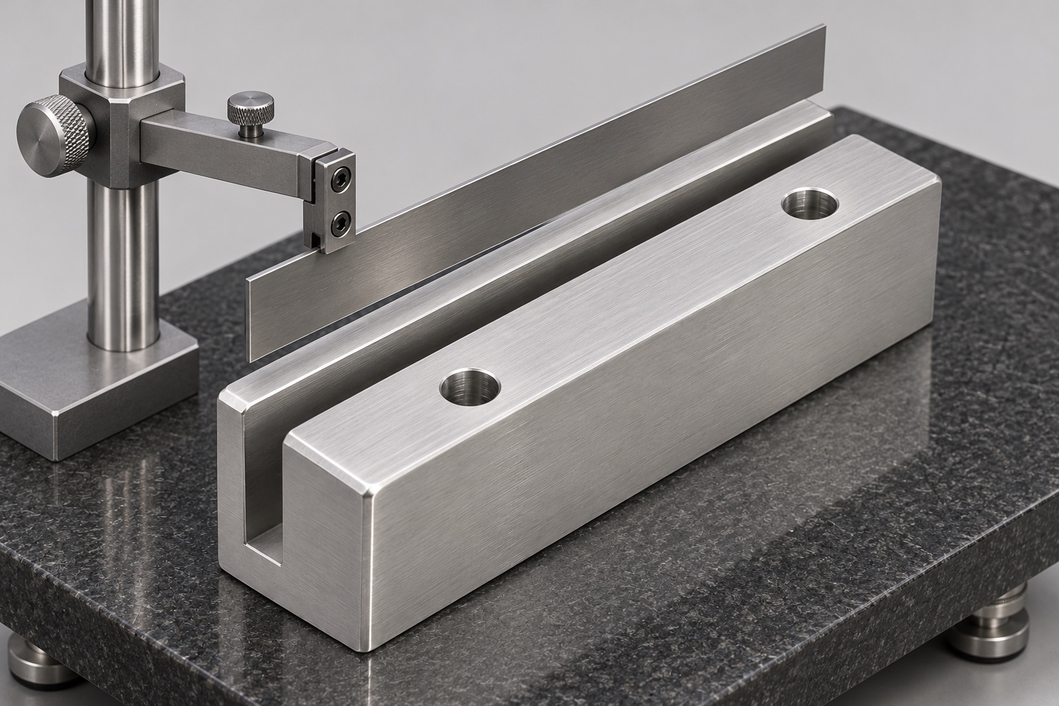
Measure the base and working channel in the inspection state stated on the drawing. A fixture can make an inconsistent underside appear stable if its clamp force pulls the block flat. Where necessary, record both the free-state base condition and a separate check at an agreed mounting condition. A depth gauge, suitable internal measurement instrument or coordinate measurement system can be selected to reach the specified surfaces. Record the accessible points, probe or gauge and reference setup. For a narrow slot, check instrument access before accepting a plan that depends on an unavailable stylus.
Use a panel coupon to investigate insertion
A clean coupon representing the specified edge can help check lead-in and seating before using a finished panel. Keep the coupon's thickness, edge condition and revision under control. Observe where it first touches and whether it can reach the intended support without force. For two mounts, define their spacing and orientation in the fixture so a problem caused by one block can be separated from a problem caused by the installation stack. A coupon fit does not prove shield retention, chemical compatibility or protective effectiveness. Any safety or equipment validation remains outside the part trial.
Document the drawing inputs for a custom order
Share a drawing, model, panel edge envelope, mounting support and relevant fastener information. Identify the intended prototype and repeat quantities separately. State which slot dimensions, burr criteria, finish records and inspection results are required. Ask the supplier to flag a conflict between the model and the released drawing rather than silently choosing the easier dimension. If the customer supplies a coupon or mating sample, define how its condition will be recorded and whether it is for reference or acceptance. This makes custom stainless CNC machining easier to compare across quotes.
Maintain a repeatable inspection record
Identify the part revision, stock lot, fixture and inspection setup on the first-piece report. Note which measurements were made before or after any final surface treatment. Where a cutter or fixture changes, review the affected characteristics rather than checking only the overall length. A width change near the bottom of the slot can point to tool deflection; a shift in the entire channel can indicate a different datum problem. Segregate questionable parts until the drawing owner approves the disposition. Keep any bench fit results distinct from actual dimensional data.
Preserve the inspected surfaces in packaging
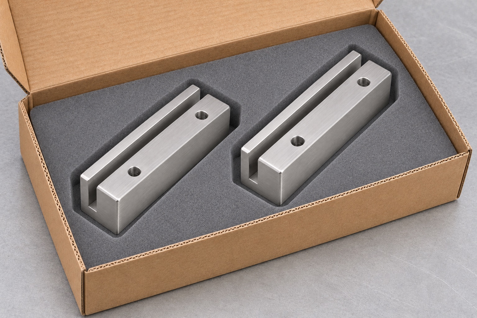
Separate mounts so a slot wall does not strike another part's base. Use a nonabrasive tray or wrap that will not shed material into the slot under the agreed shipping conditions. Keep adhesive labels away from working surfaces, and identify the lot and revision on the outer package. If a specific cleanliness level is required, define the handling and acceptance requirements before releasing the order. Ordinary protective packaging preserves surface condition and identity in transit. It is not evidence of a sterile barrier or a qualified cleaning process.
FAQ
Is the slot a clamp for the shield?
Not in this geometry. It locates and supports the specified edge. Retention is defined by the complete assembly and must not be inferred from a close fit.
Can a single thickness reading define panel clearance?
Not reliably. Consider the allowed edge envelope and any insert or finish, then check the channel where the panel engages it rather than only at its mouth.
Why measure a machined block after unclamping?
Clamping may temporarily deflect a slotted block. A free-state check can reveal this change, while a separate installed check may be needed if the drawing requires it.
What does a test coupon establish?
It shows insertion or seating under the specific conditions represented by the coupon and fixture. It does not establish retention or performance of a complete workstation shield.
Does 316L establish compatibility with cleaning chemicals?
No. Alloy, surface condition, exposure and the actual cleaning procedure all matter. The equipment owner defines and verifies compatibility independently of dimensional acceptance.
What information improves a request for quotation?
Provide the released drawing, panel and support envelopes, quantities, material and finish, critical inspection criteria and packaging requirements. Identify any open design decisions explicitly.

tanghangyun@oemach.com