
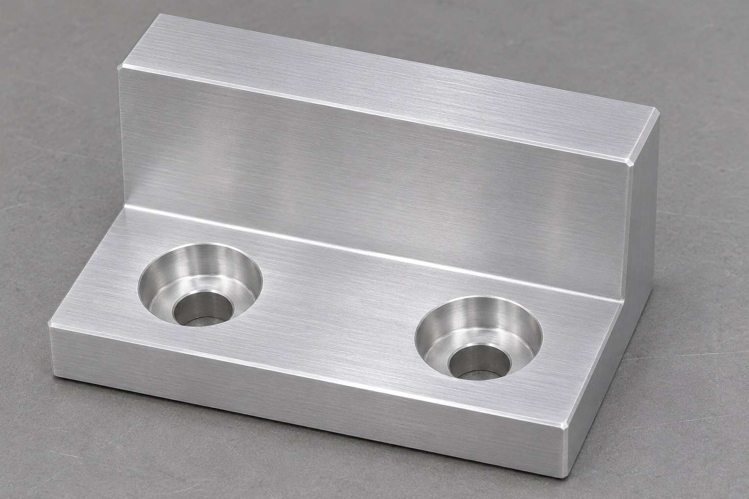
Treat the end stop as an interface, not a safety claim
An ultrasound cart can carry equipment and accessories on a chassis with purpose-built mounting features. In this guide, a generic accessory tray moves along an equipment-specific rail and meets a machined end stop. The representative part is a compact 6061 aluminum block with a raised contact shoulder, a flat base and two recessed mounting holes. It is not a cart brake, a transport restraint or a validated safety device. The machining task is to put a stable contact plane in the location defined by the drawing and leave space for the intended fasteners.

Name the surfaces that actually set the stop
Trace the tray's travel to the point where it meets the stop. The side of a fastener head, a decorative corner radius or an adjacent flange must not become the first contact unless the assembly drawing calls for it. Identify the shoulder face that sets the position and the base surface that seats against the rail. If a shallow locating step indexes the block, draw it as an interface with defined depth and side clearance. These references are useful for quoting and for checking that the stop location is not set by an unintended high point.
Dimension rail fit and contact position separately
An end stop can seat flat but still locate the tray too far along the rail. Specify the length from the locating feature to the working face and give the mating rail dimensions that establish orientation. A one-sided clearance check on a convenient rail sample cannot cover the full stack. Compare the largest and smallest allowed conditions or use a documented pair of limit fixtures where appropriate. The inspection plan should distinguish face position from hole spacing and from contact squareness. Combining them into one generic tolerance obscures the source of an assembly problem.
Select a milling sequence with accessible datums
For a prototype, machine the mounting base and a side reference on a stable blank. Locate on them to mill the shoulder and the relief next to the working contact. Keep stock and clamping clear of the tool path and use a supported setup for the recessed fastener seats. If the side reference is cut away later, use a fixture to transfer it or change the sequence. Verify that the shoulder remains square to the stated base after the part is removed. CNC milling alone does not establish the relationship if the fixtures and drawing reference different surfaces.
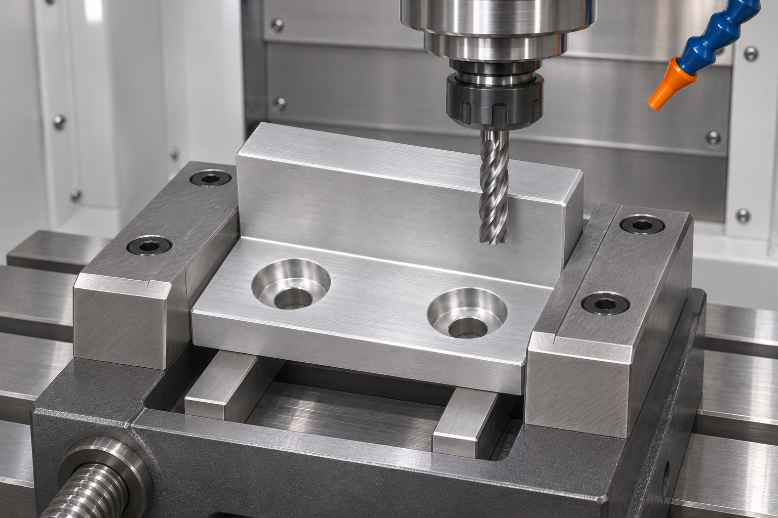
Account for tool radius and mating corners
A milled inside corner normally retains a cutter radius. A rail tongue or tray edge with a smaller corner radius can touch the leftover material and hold the stop away from its base. Identify the interference on the model and discuss a compatible relief or mating edge rather than filing parts to fit at assembly. At the contact shoulder, keep any chamfer clear of the required flat contact band. Inspect both transitions. If a working edge is meant to remain sharp within a specified limit, make that exception clear next to the general edge note.
Keep the recessed mounting seats functional
Counterbores can keep screw heads below the envelope of a sliding accessory. Specify the seat depth and diameter against the actual fastener and its tolerances. Confirm that the remaining floor thickness and head support are accepted by the assembly designer. A flush appearance alone does not confirm engagement, tightening behavior or strength. Deburr the lower exit and check that any coating does not block the clearance holes. During drawing review, request the screw type, installation condition and any special tool access constraints rather than assuming all fasteners of the same nominal diameter are interchangeable.
Specify aluminum finish at the assembled condition
Identify the 6061 stock condition and any specified anodizing or other finish. Call out the surfaces where dimensions must hold after finishing and identify allowable masking, witness marks or appearance variation. A finish can change the dimensions of a locating step or hole, so reserve allowance only with an approved process plan. Do not infer a particular finish thickness or cleaning-agent resistance from the alloy designation. If exposure to cleaners or wear is relevant, the equipment owner establishes the applicable requirements and the validation method. Separate those criteria from dimensional acceptance of the machined part.
Inspect the stop face from the rail datum
Support the base on a fixture that reflects the drawing reference. Compare the shoulder position and orientation with a suitable height, indicator or coordinate measurement strategy. Use separate measurements for the counterbore depth, through hole pattern and the locating step. If the contact plane is short, choose points far enough apart to detect angular error without crossing an edge break. Document the setup and any repeatability checks. A part that fits one assembled rail is useful evidence, but direct measurement makes it possible to explain which feature would need review if another rail does not fit.
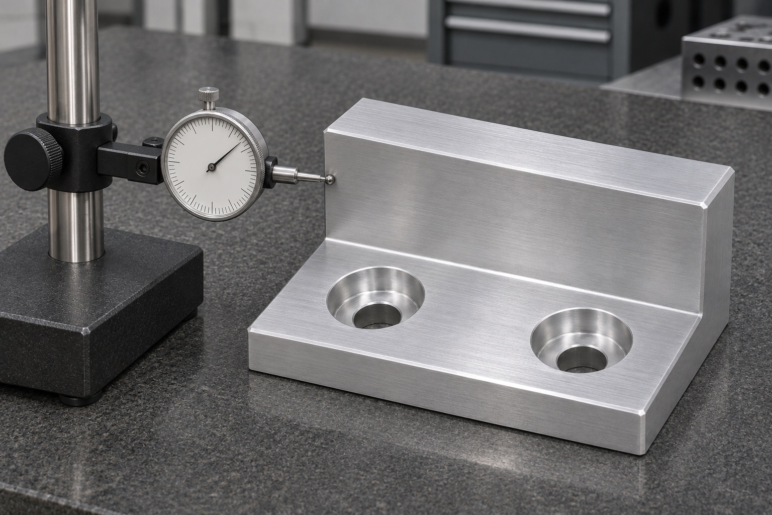
Use a controlled accessory travel check
A short representative rail segment and a mechanical tray surrogate can check end approach and contact. Slide the surrogate with the agreed clearance and observe whether it stops at the intended shoulder rather than on a screw head. Record orientation, contact location and the revision of the fixture. Do not apply an impact load in a dimensional trial or interpret a smooth slide as a strength result. The equipment designer establishes retention, impact and load requirements and tests the actual assembly when those are needed. This check only addresses a defined mechanical fit condition.
Set a first-piece plan that survives repeat orders
For prototype and low-volume work, record the drawing revision, fixture reference, stock lot and finishing status. Confirm the mounting base, step and shoulder before using the first part to judge assembly fit. If the finish is subcontracted, compare the dimensions that could change before and after finishing where the drawing requires it. For later lots, agree on renewed first-piece checks after fixture or coating changes and on how parts are segregated when an issue is found. A traceable record helps distinguish a setup shift from a revision mismatch or mating rail variation.
Quote the part with its actual rail and fastener information
To request custom CNC milling for medical cart parts, provide the current model, controlled drawing, rail envelope and fastener information. Identify which quantities are prototypes and which are repeat lot estimates. State whether the supplier should make a test fixture, inspect the face relationship or provide a coating record. Highlight areas where scratches, coating build-up or burrs could affect seating. If the device owner has not yet fixed a clearance or finish requirement, mark it as open. A quote can then identify assumptions instead of pricing a generic aluminum block that misses the assembly intent.
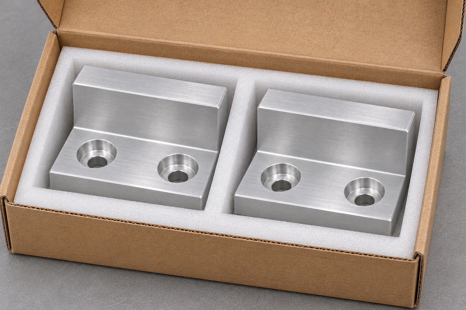
Protect both the base and the raised shoulder
In transit, a raised stop shoulder can rub against the mounting base of another part. Keep parts in divided pockets or nonabrasive individual wraps with nothing bonded to the functional faces. If finish appearance matters, agree on where packaging can touch the part and how the surfaces are inspected at receipt. Label the container with part number, revision and lot, and include any required inspection or finish documentation. Ordinary protection does not qualify a package as sterile or prove a cleanliness specification; those conditions must be defined and verified on their own.
FAQ
Does this component replace an ultrasound cart brake?
No. The example is a travel stop for a drawing-controlled accessory rail. Braking, transport restraint, impact resistance and overall cart safety are separate design and evaluation questions.
Which face should locate the inspection?
Use the base and side or step that the drawing identifies as the mounting references. Verify the working shoulder from those datums rather than from a cosmetic face.
Why measure counterbore depth after finishing?
Where the drawing applies to the final condition, finishing can alter clearance at the seat and holes. The installed fastener must remain within the specified envelope after the complete process.
What if the block rocks on the rail?
Inspect for a burr, corner interference, debris or a high area before changing the fit dimension. Verify both mating parts against the controlled drawings and document where contact occurs.
Does a smooth bench slide demonstrate load capacity?
No. A smooth trial verifies only the observed fit and contact path under the chosen conditions. Strength, repeated use and transport loads need their own evaluation.
What information helps a supplier quote accurately?
Provide the rail interface, approved fastener, drawing and model, quantity, finish, final condition and the required inspection evidence. Identify the shoulder face and allowed edge breaks explicitly.

tanghangyun@oemach.com