
Separate the carrier from the optical element
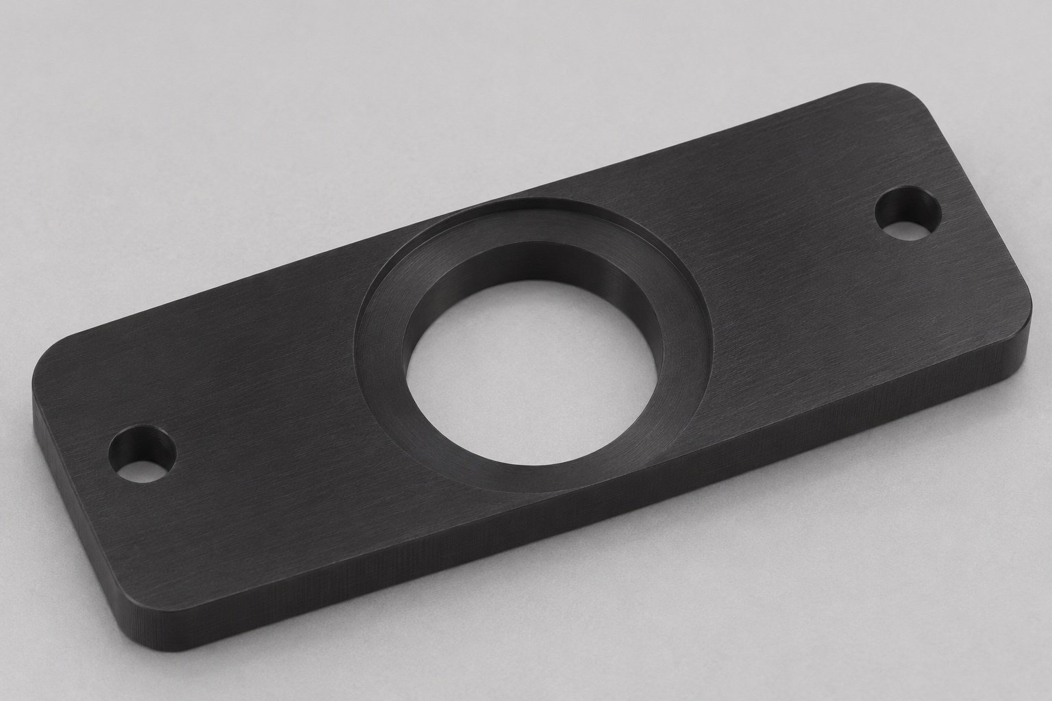
Some microplate readers use filters to select wavelengths. A machined carrier can support a filter without itself doing the optical filtering. The representative geometry here is a flat black PEEK plate with a central aperture, a shallow annular seat above that opening and two screw clearance holes. The seat supports a drawing-defined rim, while the aperture leaves a clear path through the carrier. This article concerns dimensional control of the mechanical part. It does not propose an optical specification or claim that a carrier of this shape fits any commercial reader.

Identify the three interfaces before dimensioning
The bottom mounting face, the seat that supports the filter and the aperture edge have different jobs. The mounting face controls how the carrier sits in the instrument. The seat controls support and elevation of the filter rim. The aperture must remain clear of the required optical envelope. Draw those interfaces separately and show where each measurement starts. For example, a seat depth measured from the cosmetic top face does not alone determine filter elevation relative to the mounting face if plate thickness also varies. Set tolerances according to the complete stack.
Locate the aperture from assembly datums
Clearance holes are often intended to let fasteners pass rather than locate a part precisely. If a side stop or pocket edge sets lateral position, use that feature in the datum scheme instead of assuming the hole centers define the optical axis. If the drawing deliberately uses the holes for location, specify the mating pins or other locating elements and the required fit. Keep the relationship between the circular seat and the aperture explicit. An aperture within its diameter tolerance can still clip a required envelope when displaced from the assembled reference.
Plan a CNC milling sequence that preserves the seat
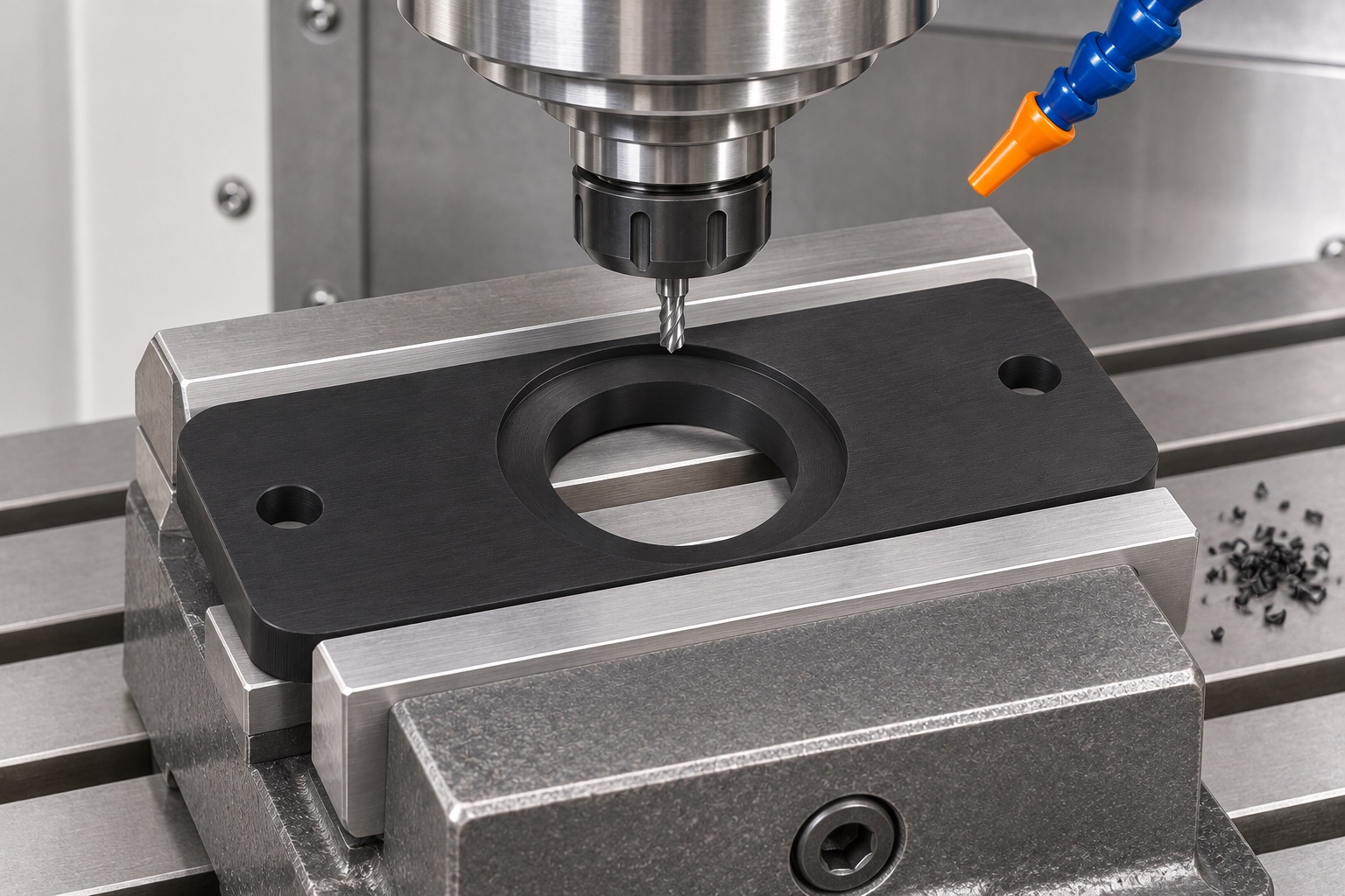
Prepare flat stock with enough allowance to finish the mounting face. Support the part under broad areas and place clamps outside the working seat. Rough the central opening and seat with enough stock remaining for a finish pass. When access allows, finish the seat and aperture in the same locating setup so their relative position is not set by two independent reclamps. Check chip evacuation, especially near the thin ledge between the counterbore and the aperture. If the part is moved for bottom work, confirm the new datum transfer before accepting final thickness.
Understand PEEK stock and clamping behavior
Specify the PEEK grade and stock form instead of purchasing by color alone. Filled and unfilled grades are not interchangeable just because they look similar. For a shallow carrier, a large clamp force can hold a bowed blank flat while cutting and hide distortion until the part is released. Inspect the geometry after unloading, in the condition stated on the drawing. If a trial shows unacceptable movement, review stock condition, tool sharpness, heat, support and the distribution of material removal. Adjust the route based on observed behavior rather than adding clamp pressure by default.
Treat color as separate from optical requirements
Black appearance does not establish transmission, reflectance, scatter or outgassing behavior for the intended instrument. If one of those properties matters, the instrument designer must state what is measured, at what conditions and on which surface. Avoid coating or abrasive treatments based solely on a desire for a darker appearance. A surface treatment may change particle generation, dimensions or fit and can create a new approval requirement. For a custom filter carrier request, list the mechanical acceptance criteria and optical or environmental tests as separate items so one is not mistaken for evidence of the other.
Keep burrs outside the optical opening
After machining, look for a raised lip, attached chip or smeared polymer at both sides of the opening. A loose strand at the entrance can be easy to see, while material on the lower side may only become visible against a contrasting background. A small controlled edge break can aid handling, but a large chamfer may remove part of the annular support. Identify permissible edge treatment on the drawing near the seat. If magnification is used for visual inspection, agree on lighting, viewing direction and defect examples to reduce variation between operators.
Verify aperture and seat with different methods
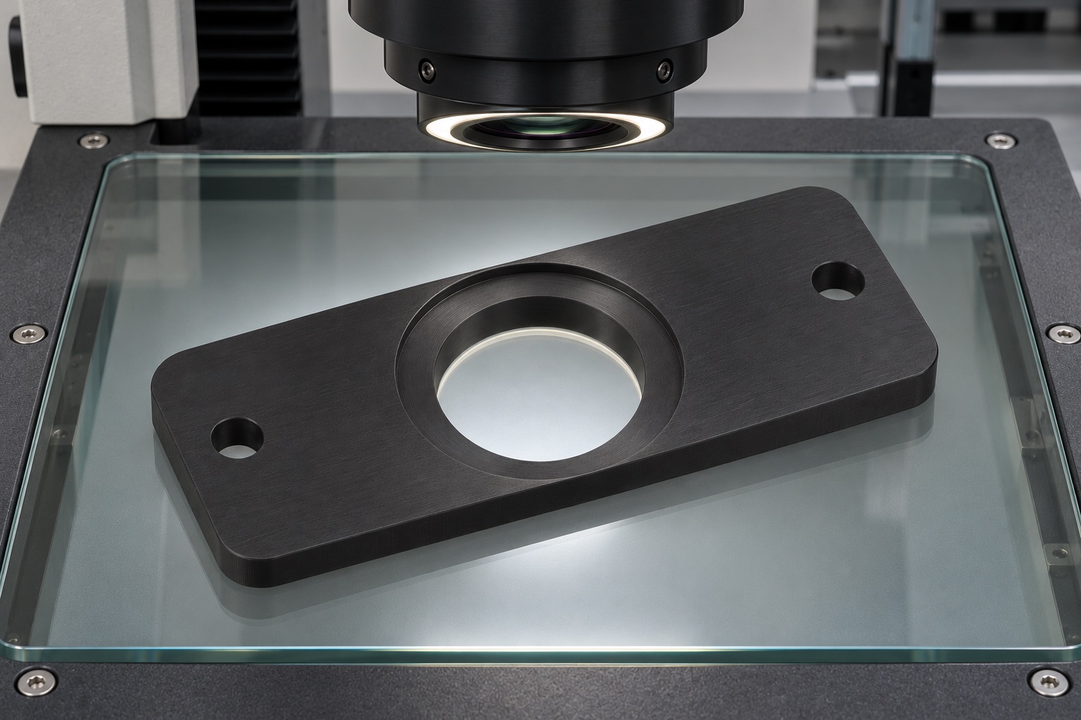
An optical measuring system can examine an accessible projected edge using controlled lighting. For a stepped opening, check which edge the instrument detects: the seat edge and the clear aperture should not be confused. Use an appropriate depth or contact method for the annular seat, with enough sampling to catch a tilted or uneven land. Very light parts can shift if touched by a probe, so use low-force support that does not flatten the plate unless a restrained check is specified. Record the datum setup and measurement strategy with the result.
Define what the mating sample represents
A non-optical ring can represent the outer rim of a filter for a handling or seating trial. Use a controlled rim diameter, thickness and corner geometry. Check for full seating and interference without pushing on a real coated surface. A surrogate ring does not reproduce optical alignment, filter fragility or thermal behavior unless those conditions are deliberately represented and validated. If there is a retaining spring or clip, agree whether it belongs in the trial. Report the result as a defined mechanical fit check rather than stating that the optical module passed.
Make prototype feedback useful for a second order
Request actual measurements for seat depth, aperture position and mounting-face flatness on the first pieces. Include the free-state support, measurement instrument and temperature conditions if they matter to the tolerance. If a change to fit is proposed, tie it to a drawing revision. Do not ask the machinist to make several untracked versions and choose the one that seems best in assembly. For a small batch, identify which dimensions are checked at set intervals and which are critical enough to check on each part, based on design risk and process evidence.
Specify what goes into a custom machining quote
Provide the drawing and model together, plus quantity, material identification, tolerances and any surface or cleanliness criteria. Mark the mounting face, seat and aperture so a supplier can see which surfaces must stay unmarked. If the clear aperture is defined by a profile rather than only a bore diameter, include the controlling geometry and the inspection datum. Specify whether the quote should cover a mating fixture, a dimensional report or protective packaging. Ask suppliers to flag unresolved requirements, rather than assuming a generic precision CNC milling claim guarantees a particular tolerance.
Prevent contact with the seat after inspection
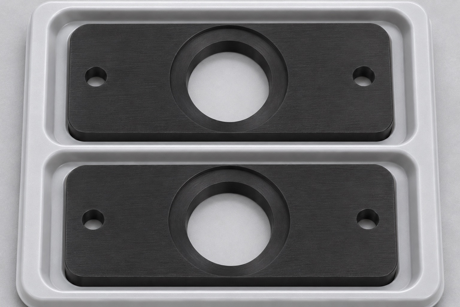
Support the carrier on allowed areas in a tray or wrapper so the seat is not rubbed by another part. Where the order specifies particle control, agree on acceptable packaging materials, handling and inspection before production. Avoid putting adhesive over the aperture or working surfaces. Label the container with part identity, revision and lot, and retain the link to the inspection record when samples are divided. Packaging can preserve the condition in which the part was released, but a sealed container alone does not demonstrate optical cleanliness or a sterile condition.
FAQ
Does a black PEEK carrier filter light?
No. In this example the carrier holds a separate optical element and leaves an opening. Any optical requirements for the carrier itself must be defined and verified independently of its color.
Can the two screw holes define the aperture position?
Only if the actual locating scheme uses them and the drawing says so. If they are clearance holes, position the aperture from the mounting surfaces and stops that actually locate the carrier.
Why measure the seat and clear aperture separately?
The annular seat supports the filter rim and determines elevation. The smaller opening provides clearance. They can have different diameters, tolerances and measurement methods, even when drawn around the same center.
Is a part measured flat in a vise necessarily flat in service?
No. Clamping may temporarily flatten or bend a polymer plate. Unless the drawing defines a restrained condition, measure it after release on supports that do not force the plate flat.
What can a surrogate filter ring confirm?
It can help check defined seating and clearance in a controlled mechanical trial. It cannot establish wavelength response, system alignment or the behavior of a real filter coating.
How should the carrier be packaged?
Use individual protection or a divided tray and avoid contact with the seat and aperture edge. If optical cleanliness is required, document the acceptance and packaging requirements separately.

tanghangyun@oemach.com