
Define the mechanical task
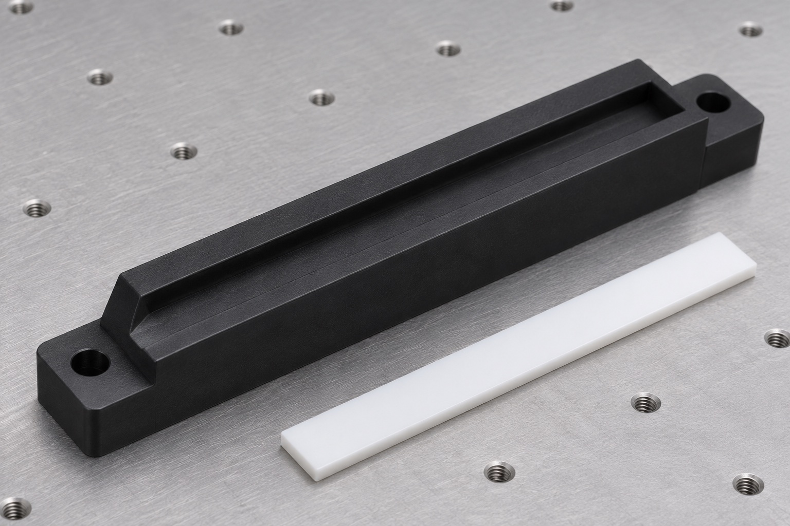
A test strip guide is a mechanical interface between a strip envelope and a loading or transport assembly. This example considers a narrow POM-C block with a shallow straight channel, a lead-in and two mounting holes. It is not a replacement for a named analyzer. Design authority remains with the instrument owner, who specifies permitted contact, geometry and material. A machining supplier can assess whether an approved drawing can be made and inspected, but cannot infer reagent compatibility, optical alignment or diagnostic performance from a channel dimension. Start with a clear boundary around the part and the evidence requested from the supplier.

Describe the strip envelope and contact zones
Request the permitted width, thickness and corner shapes of the inert reference used for fit. A nominal strip width is not enough to determine a clearance requirement. The drawing should distinguish surfaces intended to support the strip, edges that can touch it, and zones that must stay clear. Identify any feature of the mating transport mechanism that limits the lead-in envelope. Clarify whether the reference is a rigid gauge or a flexible coupon, because they respond differently to local bow or an entry defect. A visible section view is useful when different interpretations of the channel floor would otherwise produce different quotes.
Identify functional mounting datums
The guide needs to be evaluated relative to the surfaces that support it and the features that locate it. Two clearance holes may allow adjustment and need not establish the transverse position. An edge, dowel or separate bracket can provide that location. If the mounting plane is the primary datum, identify the portion of the underside that actually contacts the assembly. A raised mark on a non-contact region has a different consequence from a mark on a pad. Dimension the channel position and depth from the functional references so the inspection does not unknowingly use an exterior face chosen for convenience.
Separate width from straightness and floor height
A width reading at the center does not show that a long channel remains open at its ends. Conversely, correct width along the length does not show that the path is straight relative to mounting references. Define cross sections near entry, middle and end, and add sampling where wall thickness or tool engagement changes. The floor should be checked separately at the functional contact regions. A rounded tool transition can reduce available space without affecting width measured higher on the wall. State the height at which the width applies. Distinguish the desired sidewall shape from the intentional lead-in and any end relief.
Evaluate polymer stock and condition
Specify the exact POM-C stock description, color, approved sources and any required lot record. A similar-looking polymer is not necessarily interchangeable, and visual appearance cannot establish its formulation. Consider residual stress, conditioning and the effect of material removal on a long narrow shape. Record the environment and elapsed time required before inspection if those variables are important to the decision. A guide that looks straight in a vise may recover after release. The approved drawing should state whether dimensions apply in a free state or a defined mounted condition, rather than relying on undocumented pressure during inspection.
Support the blank without forcing it flat
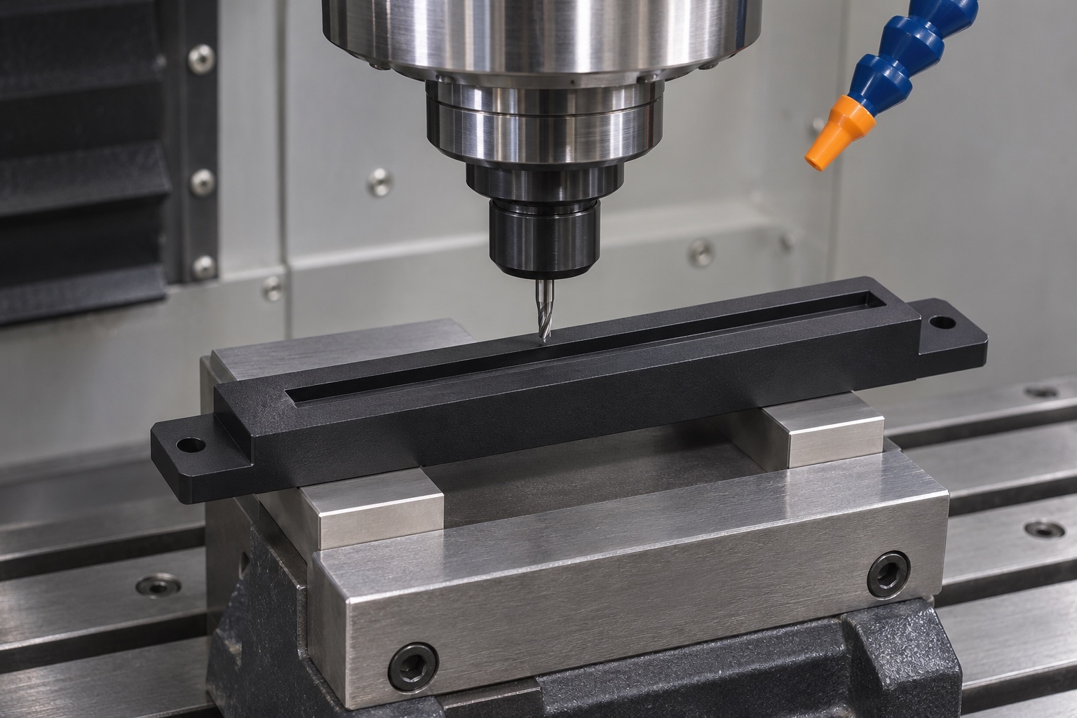
A workholding plan should keep the blank stable without masking its free shape. Provide support beneath the relevant regions, use locating stops outside the functional channel, and confirm that clamping does not bend thin walls inward. If the cutting load requires more restraint, reconsider the operation order and tool engagement before simply increasing pressure. A roughing pass can leave allowance so the part can be released and reassessed before final work. Inspect the seating faces after each transfer for particles or impressions. Any program offsets based on measurements made in the fixture should be reviewed against the released part.
Choose an entry and floor strategy
Use a cutter that can reach the channel without an unnecessary long extension. A planned corner radius is easier to repeat than an unapproved sharp corner. Decide whether the lead-in is a machined bevel, a radius or a separate transition feature, and show its boundary so that the straight locating walls retain enough length. Review tool marks at the entry and floor rather than specifying a cosmetic polish for the entire block. If a cutter is changed, verify any resulting difference at narrow sections and at the end of the channel. Control the sequence so that deburring cannot change the accepted width.
Remove burrs without rounding references
POM-C can leave small raised edges or curled chips at the channel rim and hole exits. Use agreed edge limits and a removal method suited to the feature. Distinguish a loose particle from displaced material and from a designed chamfer. Aggressive hand finishing can widen an entry unevenly or round the edges used as a dimensional reference. Check that the floor and mounting pads are not marked during cleanup. Inspection should include light and viewing angles that reveal raised edges without treating a smooth-looking surface as evidence of dimensional conformance. Keep the acceptance criteria tied to the drawing and the intended contact zones.
Compare free and installed conditions explicitly
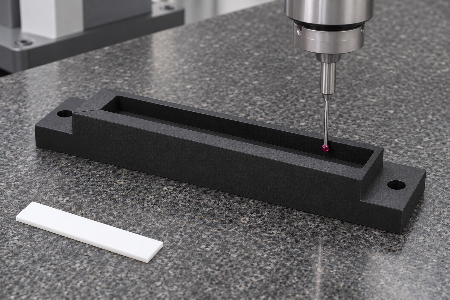
Free-state inspection can reveal bow that disappears when the guide is mounted. If assembly constraints matter, specify the support surfaces, fastening sequence and approved mounting condition for a second check. Do not press the part flat to obtain a reading without documenting it. Report which condition was used for each result. Measurements from an unconstrained bench and a constrained fixture can both be useful, but they answer different questions. If an apparent mismatch occurs, check fixture flatness, trapped debris and the location of the measuring force before deciding that either the part or the instrument is wrong.
Use a dry mechanical reference
A clean inert coupon or agreed gauge can reveal where an entry catches or where the channel binds. Record its dimensions, orientation and condition. A rigid coupon tests the available geometry under a specific setup, not transport reliability with a flexible strip. If contact occurs, inspect the entry edge, floor and opposite walls before changing nominal width. A dry check should use no biological specimen, reagent or operating analyzer. It is an addition to dimensional inspection, not a substitute for a validated workflow or a demonstration of diagnostic accuracy. Distinguish the observation from the design conclusion in the report.
Protect the guide during storage and transport
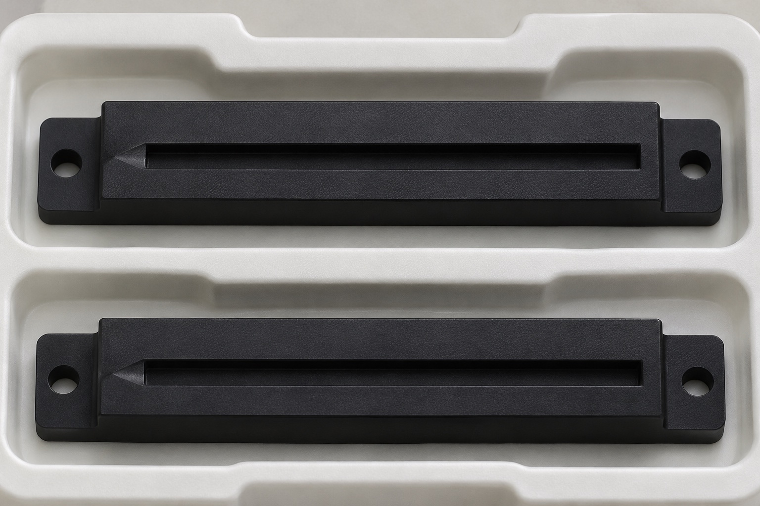
After agreed cleaning, check the channel for debris and inspect the thin walls. Choose packaging supports that avoid long-term bending or pressure on the rim. Separate parts so mounting ears and guide edges do not strike adjacent components. Label the package with the revision and lot references requested for the job, rather than placing adhesive on a functional surface. A clean packing area and protective trays do not imply sterilization or a validated cleanliness level. Where those conditions are required, agree a documented process and verification criteria before quoting. Otherwise report the actual protective measures and the agreed delivery condition.
Build an actionable machining inquiry
Include the revision-controlled drawing and model, strip envelope, location of permitted contact, mounting references, stock requirement and delivery quantity. Ask the supplier to explain channel access and the proposed clamping and inspection condition. Specify where width and floor readings are needed, and provide the agreed inert reference if a fit check is requested. Identify which evidence belongs to dimensional release and which belongs to the instrument owner. Clear requirements reduce the risk of modifying a part to suit an unsuitable fixture. They also allow a supplier to flag narrow corners or unsupported walls before producing a first article.
FAQ
Does a center width measurement prove channel fit?
No. Width may vary along the channel and at different wall heights. Check the specified sections, straightness and entry condition against the agreed strip envelope.
Why record the free state?
Clamping can conceal bow or temporarily shift a thin wall. A free-state check helps distinguish the part's released shape from the condition imposed by a fixture.
Can a rigid coupon validate analyzer transport?
No. It can reveal a geometric obstruction in the agreed bench setup. Flexible strip behavior, timing and diagnostic performance require separate evaluation by the device owner.
Should both mounting holes define location?
Only if that is the approved design. Clearance holes may provide fastening without establishing location. Identify the actual locating feature and datum scheme on the drawing.
Does POM-C alone establish reagent compatibility?
No. Exact grade and exposure conditions matter. Chemical and diagnostic suitability are outside this machining review unless separately specified and validated.
What packaging features protect the channel?
Use supports that keep pressure away from the rim, separate adjacent parts and maintain the agreed cleanliness and identification during handling.

tanghangyun@oemach.com