
Define the cable clamp base's mechanical scope
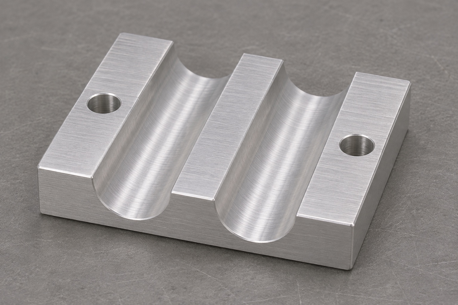
A portable EEG amplifier cable clamp base is a mechanical component that supports an assembly interface. The representative part discussed here is only the lower aluminum half: a rectangular base with two parallel open channels, flat mating lands and two mounting holes in the outer lands. A separately designed cover and the actual cable are outside this geometry. Precision aluminum machining should reproduce the approved interfaces without implying electrical or clinical performance. This guide does not establish shielding, insulation, strain-relief force, signal quality or patient safety, and it provides no instructions for modifying a medical electrical system.

Start from the approved cable and cover envelope
The channel geometry needs a design basis rather than a convenient cutter diameter. Ask the design owner to identify the cable envelope, intended contact region, cover relationship and required clearances. These inputs determine which channel surfaces are functional and which are merely access or relief features. An open lower channel cannot establish the completed assembly's clamping behavior by itself. Keep the review focused on controlled mechanical requirements, and refer electrical or system-level questions to the responsible team. A supplier should not select an unknown cable or invent a squeeze amount while preparing a machining quotation.
Specify 6061 beyond a generic alloy label
The material requirement should identify the applicable specification, temper, supply form and traceability expected for the order. A generic request for aluminum does not establish the blank condition used to plan the route. If a secondary surface treatment is required, its scope and any dimensional implications should be reviewed with the drawing. Do not infer an electrical property or a medical-use approval from the alloy designation. Material documentation can confirm specified identity within its scope, but it does not validate the finished cable clamp assembly or demonstrate its behavior under an unknown operating environment.
Establish mounting and mating references deliberately
The underside may locate the base on its supporting structure, while upper lands mate with a separate cover. The drawing should distinguish these roles and identify how the open channels relate to them. A process plan can then choose a reference sequence that avoids accumulating uncontrolled transfers. When a surface is held for machining, the fixture should support the base without damaging a finished land or distorting the channel region. Adding more axes does not automatically resolve a poor reference strategy. The important evidence is a controlled relationship between the actual mounting, mating and channel features.
Choose a CNC milling route for open channels
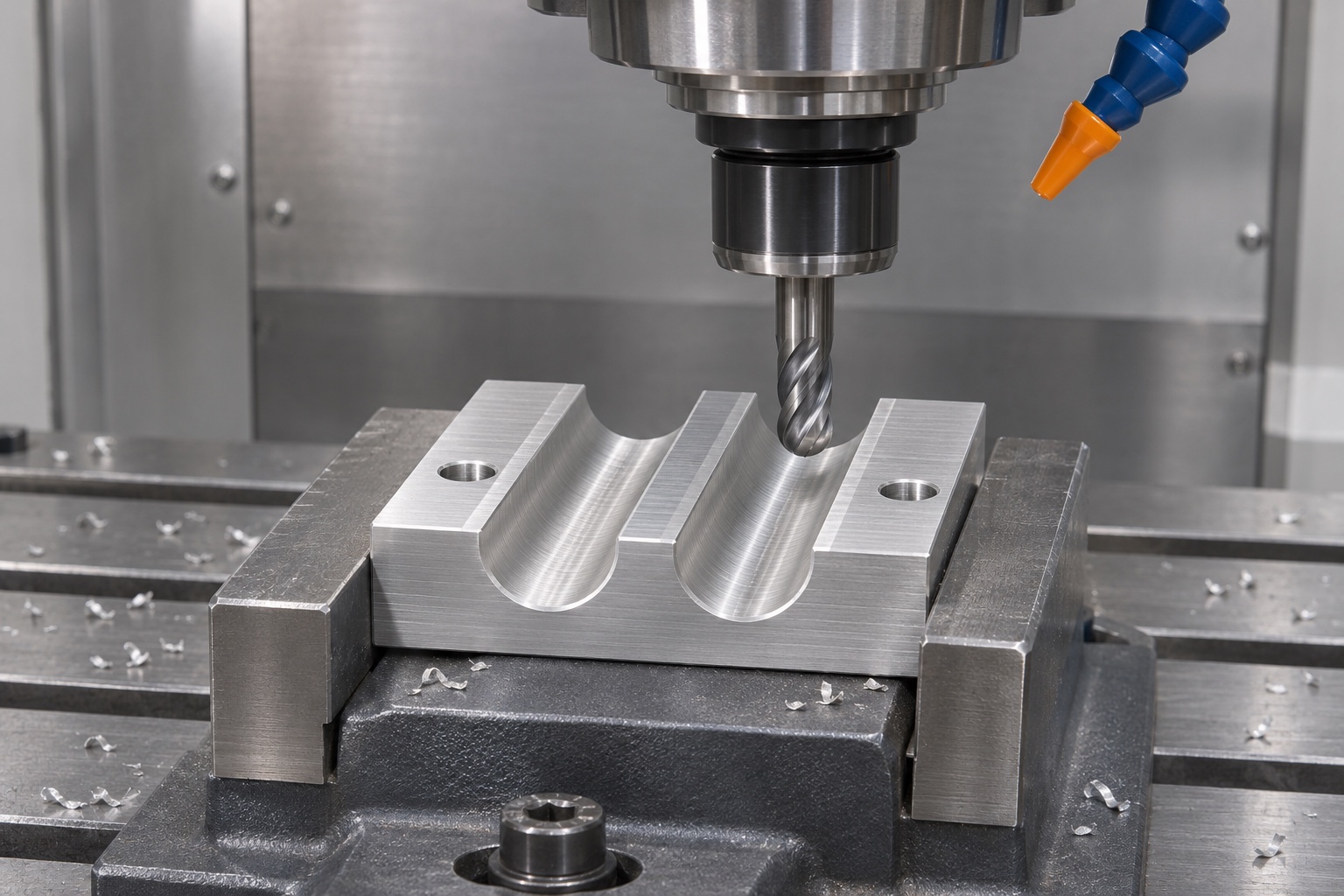
Open channels often provide straightforward cutter access, but their profile and end conditions still need review. The route may combine roughing with a dedicated finishing operation to achieve the approved shape while retaining stable support. Cutter choice should follow the channel geometry, access and finish requirement rather than redefine them. Decide whether the channel ends need a specified edge condition or a transition into adjacent surfaces. The example uses two parallel channels and two outer mounting holes; additional slots, covers or hidden features should not be added simply to make a manufacturing photograph look more complex.
Distinguish profile requirements from surface appearance
A smooth channel can still have the wrong radius, depth or relationship to a mating land. Define the geometric characteristics that affect the intended mechanical interface and specify texture separately where needed. A single roughness value does not describe an entire channel profile. If the design uses a semicircular section, its location and useful contact length still need definition; if another section is required, show it explicitly. Avoid universal promises that polishing will improve cable retention. Retention belongs to the complete approved assembly and must not be inferred from the appearance of a lower clamp half.
Keep mating lands consistent without inventing closure
Flat mating lands provide a relationship to the separate cover, but the base drawing must state what is controlled about those surfaces. Their level, orientation and permitted interruptions depend on the design. A machining supplier should not assume that the cover must close metal-to-metal or that a visible gap is automatically unacceptable. Those are assembly decisions. Review the relevant envelope and acceptance criteria before finishing the lands. During handling and secondary operations, protect them from raised marks or trapped chips that could affect inspection. Cosmetic blending should not remove material from a controlled mating surface without authorization.
Relate mounting holes to the supporting structure
The two outer mounting holes should be defined against the base's approved reference system. Clearance, counterbore details or thread requirements must come from the drawing; this example does not infer hidden fastening features from a photograph. Plan access for machining and inspection without using the open channels as convenient clamping points. Mounting-hole acceptance addresses the component geometry, not the strength of the installed system. Fastener selection, tightening conditions and the supporting structure require their own design review. Keep those responsibilities explicit so a machining inspection report is not presented as approval of the complete mounting arrangement.
Plan finishing around edges and contact surfaces
The edges at channel entrances, mating lands and mounting holes deserve a controlled finishing plan. Remove unwanted projections within the specified allowance while preserving functional geometry. A broad instruction to soften every edge can erase a boundary that the design intended to control. If anodizing or another treatment is requested, specify the process and identify which features require acceptance after treatment. Do not describe a coating as proof of electrical insulation or medical suitability without the relevant design and evidence. The machining route should state exactly which surface operations are included and which conclusions remain outside its scope.
Inspect accessible profiles with a suitable method
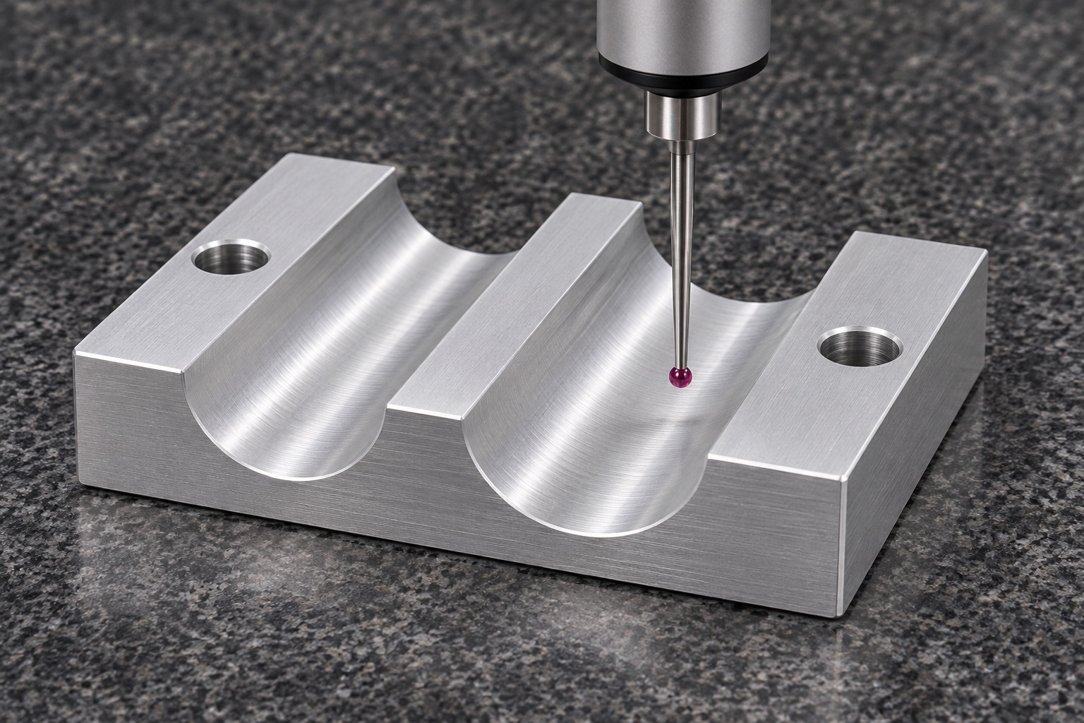
An inspection plan can combine checks of the mounting underside, mating lands, channel locations, channel profile and hole characteristics. Choose methods that can access the relevant channel surfaces with an appropriate reference alignment. A CMM, optical method or dedicated gauge may each be suitable for particular characteristics, but the method must match the feature and acceptance requirement. A photograph alone cannot establish depth or profile conformity. Record the agreed results and any limitations, especially when a proposed method samples only selected sections rather than the full useful contact length of both channels.
Preserve accepted surfaces through packing
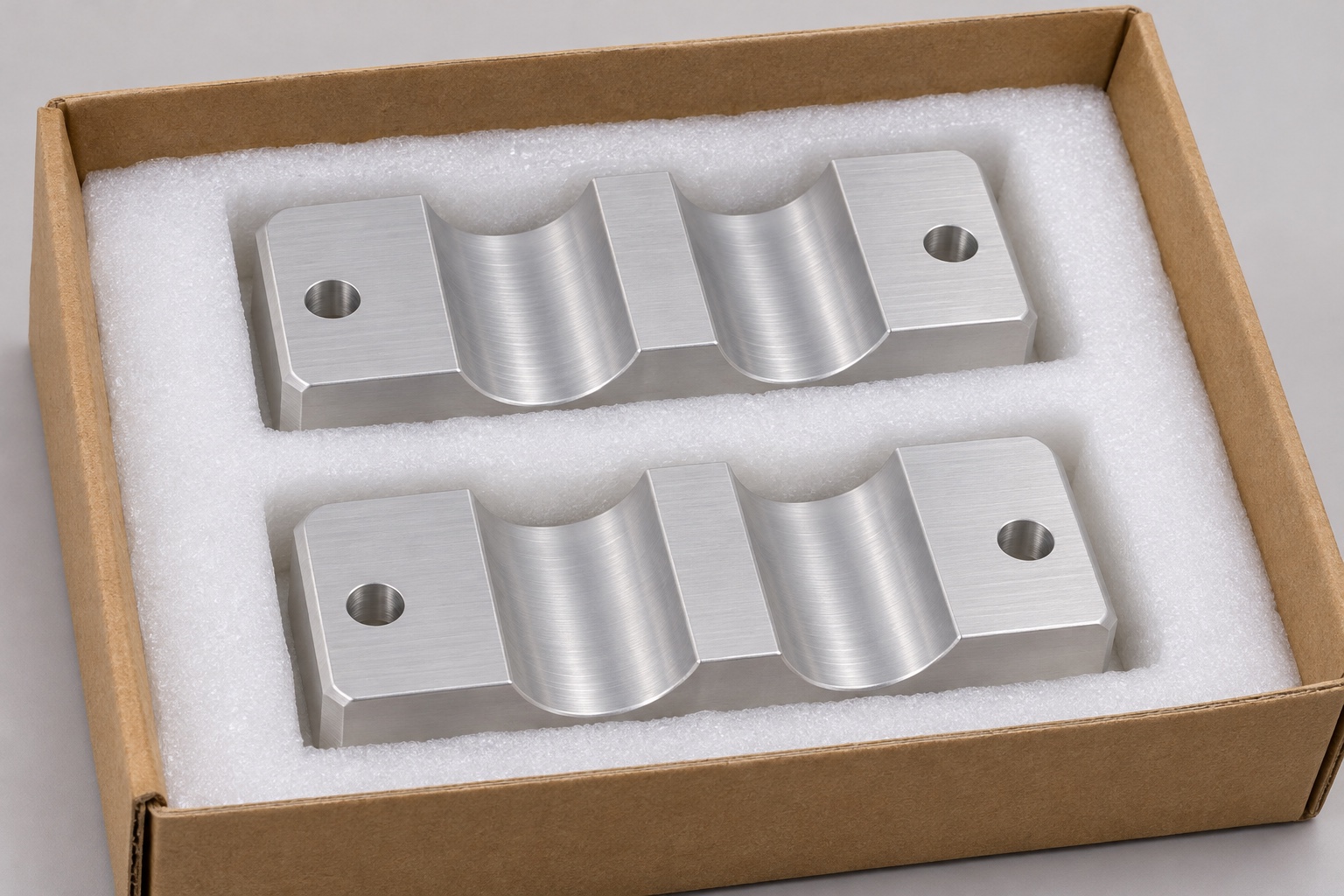
Final preparation should remove loose machining residues within the agreed scope and keep the open channels available for examination. Protect mating lands from impacts, adhesive labels and contact with loose fasteners during packing. Separate pockets can support the base without placing pressure across delicate edges. The actual packing material should be compatible with the specified downstream handling requirements. This is a component protection measure, not a sterile packaging claim or an assertion about electrical cleanliness. Any additional preparation, environment or validation requirements must be stated separately so the shipment record reflects work actually performed.
Write an RFQ that separates component and system evidence
An RFQ for custom EEG equipment cable clamp components should provide the controlled drawing, model revision, material condition, quantity, surface treatment and inspection deliverables. Include the mechanical mating envelope when it is needed to resolve channel and land requirements. State whether the supplier is asked only to manufacture the lower half or also to perform an approved assembly evaluation. Keep electrical, signal and patient-related validation outside an ordinary machining claim. Comparing quotations on the same scope makes cost and schedule differences easier to understand and helps prevent unsupported performance language from replacing reviewable engineering information.
FAQ
Does the lower base establish cable retention force?
No. Retention depends on the complete approved assembly, cable and installation conditions. Channel dimensions are component characteristics; they cannot by themselves establish a strain-relief force or a safe operating condition for the equipment.
Can a cutter diameter define the channel design?
It can inform a manufacturability discussion, but the approved design determines the profile. The supplier should propose any change explicitly rather than replace required geometry with the shape of an available cutter.
Does 6061 identify the full material requirement?
No. Specification, temper, stock form and required documentation still need definition. An alloy name does not establish the finished component's electrical behavior, medical suitability or compatibility with an unspecified secondary treatment.
Should the mating lands always close metal-to-metal?
Not necessarily. Closure and permitted gaps depend on the approved cover and cable assembly. The base drawing should define the controlled surfaces without requiring the machinist to invent the complete clamping arrangement.
Can an inspection photograph prove channel conformity?
No. Photographs can document appearance and access, but relevant dimensions and profile relationships need suitable measurement methods. The report should describe the reference alignment, sampled locations and actual acceptance evidence.
What should a prototype submission avoid claiming?
It should avoid unsupported shielding, insulation, EEG signal quality, retention-force or clinical claims. Report real component evidence against the approved scope, and identify any assembly or system requirements that remain for the responsible design team.

tanghangyun@oemach.com