
Keep the mechanical block separate from switch approval
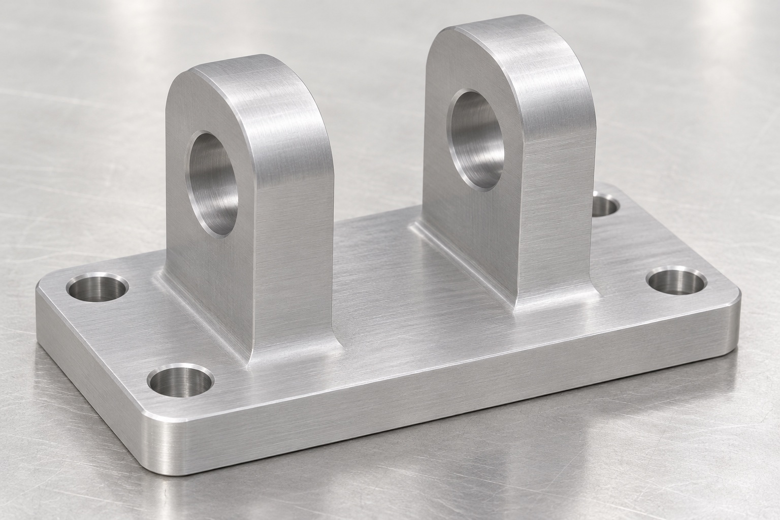
6061 CNC milling for an electrosurgical footswitch hinge block concerns a specified mechanical interface, not the electrical or clinical performance of a footswitch. The representative component is a rectangular aluminum base with two raised hinge ears, aligned pivot bores and mounting holes. This guide discusses manufacturing and dimensional acceptance of that geometry. It provides no instructions for wiring, adjusting or repairing an electrosurgical device. The application name does not establish replacement compatibility, load capacity, ingress protection or electrical safety. Those matters require approved system requirements and separate evaluation by the responsible device organization before an actual component is used.

Define the pivot axis and its reference
The drawing should identify the intended pivot axis and its relationship to the mounting references. Two holes with acceptable individual diameters do not necessarily establish an acceptable shared axis. Clarify which surfaces establish the block's position during inspection and how the axis is recovered. Do not treat a shaft pushed through both holes as a complete measurement of every required relationship. Where a documented inert pin is part of the inspection method, specify its geometry and the observation it supports. The supplier needs controlled requirements rather than a generic instruction that the pedal should move freely after assembly.
Specify ear spacing and usable side contacts
The space between the raised ears must be defined relative to any approved mating part, including useful side-contact regions and permitted clearances. Overall block width does not establish this internal relationship. Distinguish the working ear faces from reliefs, entry features and edge breaks. Provide the mating envelope where it controls access or interference. Do not infer a complete pedal assembly from a photograph of a hinge. The supplier should know which surfaces may touch and which must remain clear. This avoids removing material indiscriminately when a fit trial encounters local contact that was never clearly defined in the enquiry.
Relate the mounting pattern to the pivot
Mounting holes locate the block in its surrounding base or enclosure. Their pattern and seating surfaces should be related to the pivot axis through the approved datum scheme. A fastener that passes through one hole does not verify the pattern or the assembled position. If the design includes recesses, slots or a raised seat, define their useful dimensions separately. The intended hardware and mounting condition should be supplied where they influence acceptance. Do not use arbitrary tightening to pull the block into a preferred position. The drawing must establish whether acceptance is in the free state or in a specified mounted state.
Confirm aluminum condition and final finish
Specify the approved 6061 material condition, stock form and documentation requirements. The alloy number alone does not define every material or final-surface requirement. Any approved anodizing, other treatment or marking should have an explicit scope, including dimensions that apply afterward. A finished appearance is not proof of electrical insulation, corrosion-test performance, cleaning compatibility or medical qualification. Those properties cannot be inferred from a photograph or material label. The supplier's inspection record should identify the actual final state, so a pre-treatment bore measurement is not silently presented as evidence for a dimension that applies after a later operation.
Plan tool access around the raised ears
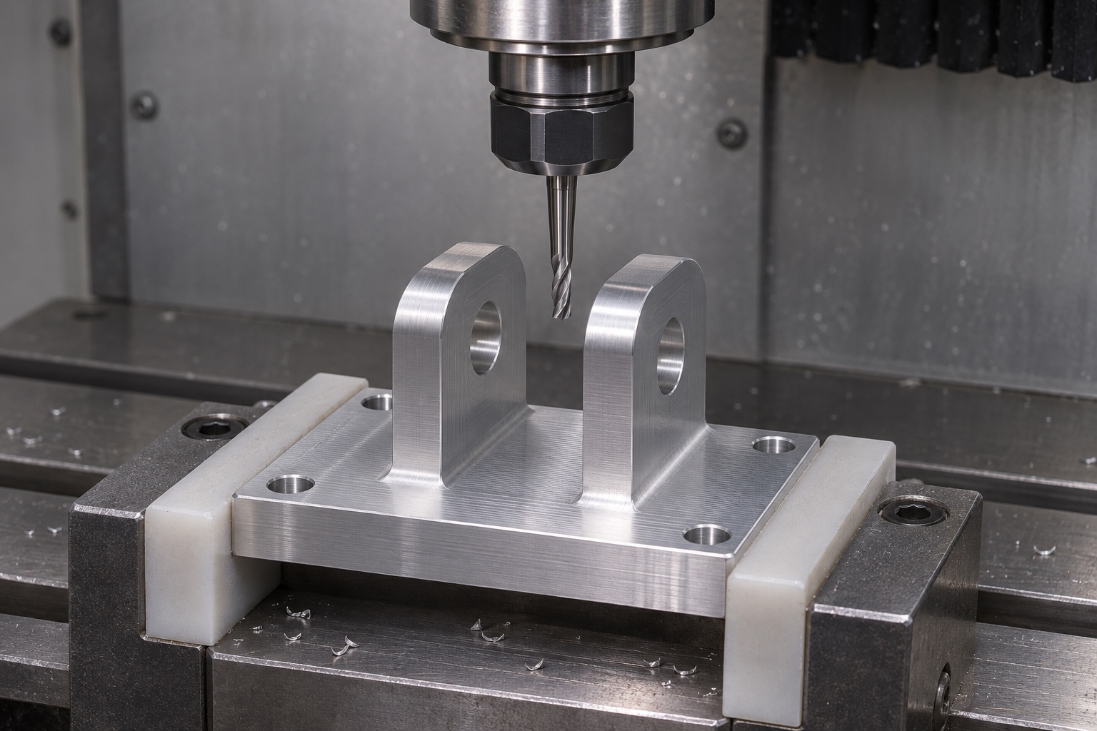
The machining review should consider access to the base, ear faces, pivot holes and mounting features while enough material remains to support the work. The actual sequence depends on dimensions, stock and equipment; this guide does not prescribe feeds, speeds or a fixed number of axes. Identify which relationships can be produced together and which require transfer. A narrow space between ears may restrict tool or probe access even when it appears straightforward in a model. Resolve those constraints before production rather than altering the useful contact faces at the machine to accommodate a tool selected after quotation.
Recover the axis across secondary operations
If the pivot features are made from different directions or after a reversal, describe how the reference is recovered and checked. A shared fixture or nominally aligned toolpath is not by itself evidence that the final holes meet the specified relationship. Protect finished seating surfaces during remaining work. Where an ear is slender, review how support and cutting forces could influence the observed geometry. A process change intended to simplify access must not silently move the pivot axis or change the approved ear spacing. The final acceptance plan should cover the actual component after all operations capable of affecting the relevant features.
Finish edges without reducing functional support
Bore entries, ear edges, mounting holes and the base perimeter need an agreed edge condition. Removing raised material should not shorten a useful pivot support length or erase an intended side-contact band. Identify which features must be rechecked after finishing. A smooth exposed edge does not demonstrate the condition of an inaccessible bore intersection. Any special cleanliness requirement must be defined independently of ordinary chip removal. This guide does not claim sterile delivery, validated disinfection or suitability for a particular cleaning agent. Protective handling should preserve the specified geometry without implying that a manufacturing operation has qualified the complete medical switch.
Select measurements for the required relationships
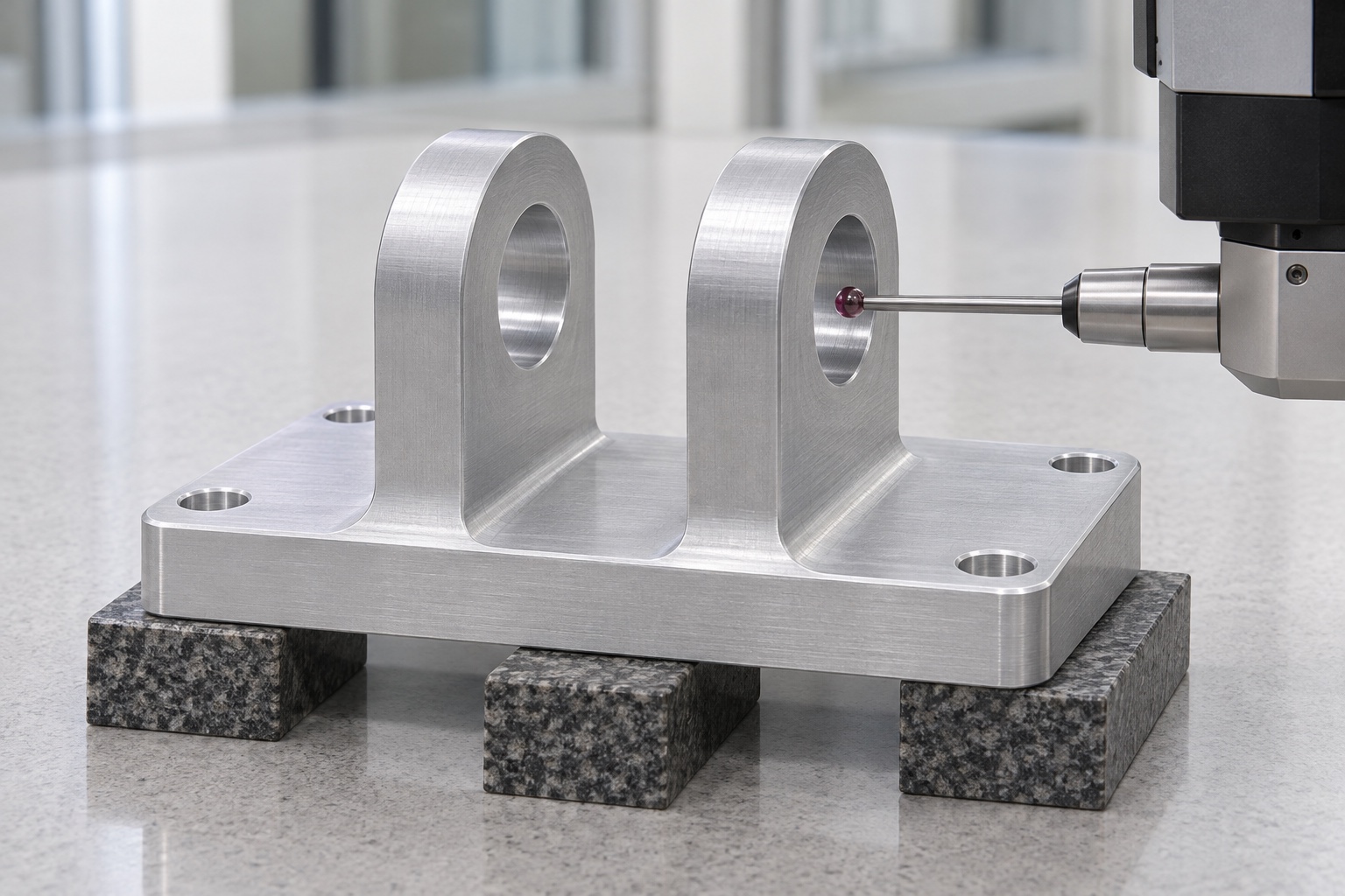
The inspection plan should distinguish individual bore size, the relationship between bores, axis position, ear spacing, mounting-pattern location and seating geometry. Choose methods according to access and the characteristic being checked. A coordinate or optical system still needs an appropriate reference scheme and defined part state. Record instrument identity and the controlled revision with actual results. No tolerance or measured value is invented in this article. For a real order, the acceptance limits must come from the approved requirements, and the selected methods must be capable of evaluating the useful surfaces rather than only the most accessible points.
Limit a pin trial to geometric observations
A documented inert pin and approved mating reference can help observe contact, passage and clearance without assembling or operating an electrical footswitch. Record the reference identity, direction and support. Do not hammer a pin through an unexplained resistance or treat a forced fit as a successful test. A geometric trial does not establish pedal force, return behaviour, switching reliability, fatigue life, electrical safety or ingress protection. Those require separate system definitions and evidence. The supplier should report the actual observation and its limits rather than convert a freely passing pin into a claim that the complete device is safe or qualified.
Diagnose binding before enlarging the holes
If an inert reference passes one ear but not the other, review alignment, bore entry edges, support, reference condition and the approved interpretation. Increasing both diameters might conceal an axis problem while changing the intended pivot interface. Preserve the original observation before corrective work. A manufacturing deviation requires an authorized disposition, while conflicting interface requirements require clarification or revision. Reinspect affected characteristics after approved correction in the defined final condition. Record the same reference identity where comparisons are intended, so changing the pin or support does not silently turn two different trials into a misleading before-and-after result.
Prepare a verifiable RFQ and packaging plan
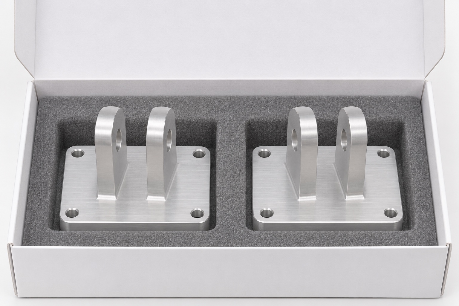
A complete machining enquiry includes approved model and drawing, revision, material condition, quantity, final finish, pivot definition, ear spacing, mounting references, mating envelope, inspection evidence and protective packaging requirements. Identify any feature whose acceptance applies after treatment. Separate blocks so ear edges and pivot entries cannot strike neighbouring metal components during transport. Packaging should support the base without squeezing the ears together or leaving fragments inside bores. Keep part identity and records associated with the shipment. This gives a medical equipment machining supplier a defined component to quote while leaving switch approval and operating performance with the responsible device organization.
FAQ
Do two acceptable hole diameters prove a shared pivot axis?
No. Individual size and the relationship between bores are different characteristics. The drawing and inspection plan must address the required alignment separately.
Can a passing pin qualify an electrosurgical footswitch?
No. It provides a limited geometric observation, not switching reliability, pedal behaviour, electrical safety, ingress protection or service-life evidence.
Why specify the space between the ears?
It defines an interface that overall width does not establish. Useful side contacts, clearances and approved mating geometry should be distinguished explicitly.
Does anodized aluminum automatically provide electrical insulation?
No such conclusion follows from a finish name or photograph. Any electrical function needs separate approved requirements and verification for the actual device.
Should binding be corrected by enlarging every bore?
Not without diagnosis and authorization. Review axis relationships, edges, support and references first, then reinspect affected features after any approved correction.
What should a buyer provide for quotation?
Send approved files, material condition, quantity, final finish, pivot and mounting definitions, mating envelope, inspection scope and protective packaging instructions.

tanghangyun@oemach.com