
Keep the example's scope explicit
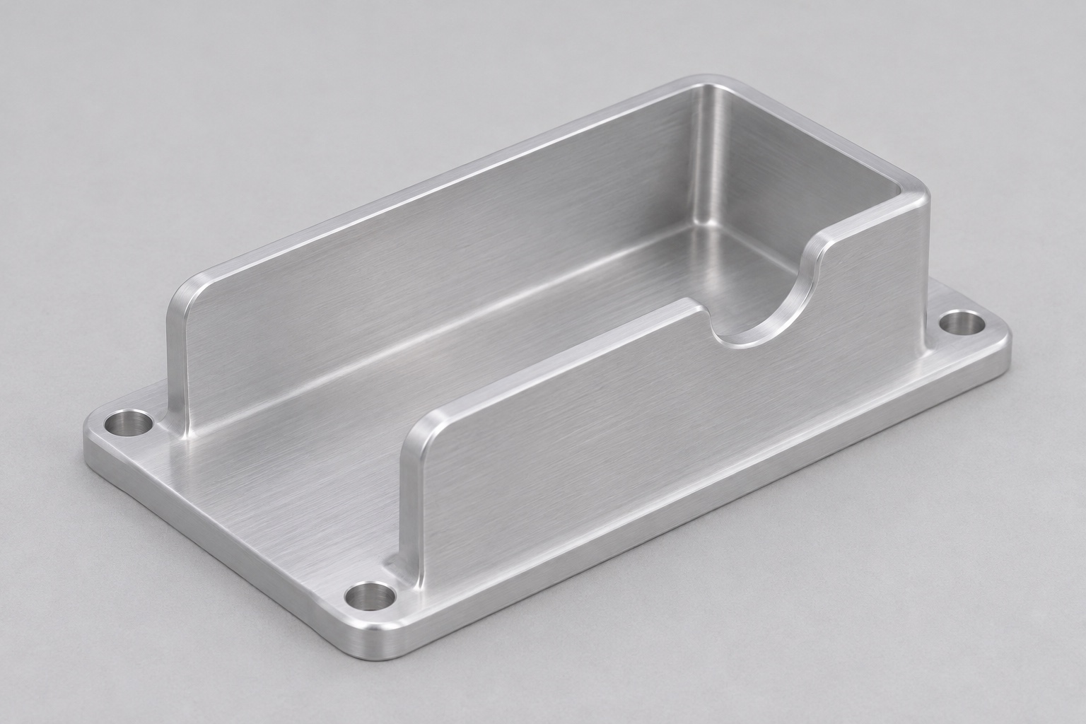
This representative CNC milling case considers a 6061 aluminum connector guard for the housing context of a portable radiography detector. It is not an account of a delivered customer project, certified accessory or tested protection device. No measurement results, shielding capability, impact rating or electrical safety claim is made. The purpose is to explain the requirements needed to manufacture and inspect a mechanical component with a base, side walls, connector space and access opening. A real project must provide approved files and acceptance criteria. Qualification of the detector and any protection functions remains separate from the machining supplier's evidence about component geometry.

Divide the geometry into functional regions
The considered shape has a mounting base and two side walls around an open connector region. An access feature leaves room for a separately specified inert envelope. The drawing must identify seating lands, lateral references, mounting holes and regions intended only to provide clearance. Not every internal wall should be assumed to touch or restrain the connector. The part name does not specify a universal guard design. A controlled definition lets the supplier inspect a standalone component without a functioning detector. It also prevents an easy exterior measurement from becoming the sole acceptance check for a more complex internal envelope and mounting relationship.
Establish the real quotation package
An actual inquiry would include consistent model and drawing revisions, the requested 6061 condition, quantity, material documents and final finish. Approved connector and adjacent housing geometry are needed when they govern clearance or mounting. The buyer should state required inspection evidence and packaging protection. A front-view photograph is not a substitute for a three-dimensional envelope or installation path. The order should distinguish dimensional inspection from any later test of protection, electrical behavior or detector performance. That shared scope allows suppliers to quote the same component instead of silently making different assumptions about cable access, internal corner relief or the finished state of thin walls.
Review the envelope before machining the cavity
The proposed manufacturing review compares the internal cavity with the approved connector and retention hardware. It distinguishes the installed volume from the path needed for insertion or removal. A component can fit locally in one view and still encounter interference behind the opening. If a relief or radius change is proposed, the designer must approve it before the files are updated. The supplier should not enlarge the whole cavity until an unidentified plug appears to fit. This case describes the review approach, not an already accepted tool route or prototype. Actual access and remaining material must be evaluated for the real drawing and equipment.

Confirm aluminum identity and final state
For a real project, incoming material and documents would be checked against the requested alloy condition and traceability scope. Similar color is not evidence that another alloy is equivalent. Any external finishing process needs defined masked areas and final-state dimensions. This representative case does not choose a coating conductivity, corrosion rating or friction value. The specified finish remains linked to the controlled revision. An observation on an unfinished guard cannot automatically be reported as evidence about the final component. The plan identifies which geometry must be checked after operations that could affect seating, hole size or available connector clearance in the accepted delivery state.
Plan the base and wall operations together
The proposed route considers the mounting plane, cavity and side walls as related features. Removing a broad pocket changes the structure supporting the remaining walls. The supplier would review tool approach, reach, chip exit and contact regions throughout the sequence. A setup suitable for the solid blank may no longer be suitable near completion. No cycle time, universal feeds or process capability is invented. The plan identifies reference surfaces and their transfer between operations, including checks after subsequent cutting. This is more useful than assuming that a completed milling program proves all internal and external relationships of a thin-walled medical equipment component.
Locate mounting holes and the access profile
Mounting holes require position relative to the seating lands and internal envelope, not merely correct individual diameters. The access window or notch also needs a defined profile and location. The design owner supplies cable and connector requirements where they influence the space. The machining supplier does not invent bend limits or claim strain relief from a rounded opening. The review includes access for finishing both sides of the window and relevant hole mouths. If another housing piece governs the available rear volume, its geometry belongs in the package. The result is an identifiable manufacturing task rather than an informal fit adjustment performed around available hardware.
Distinguish workholding from the required shape
The proposed fixture supports permitted base regions without spreading or squeezing the side walls into an unrecorded state. The inspection condition is agreed separately. A free-state requirement is not verified by pushing the base flat against a fixture; a specified mounted state needs its own reproducible support and hardware. This example contains no measurements under either condition. It emphasizes that a discrepancy should trigger review of references, clamping and finish before material is removed. Otherwise, a correction might simply reproduce one fixture's effect and leave the actual component requirement unresolved. The original observation is retained so a later inspector can understand the decision.
Finish edges and inspect affected geometry
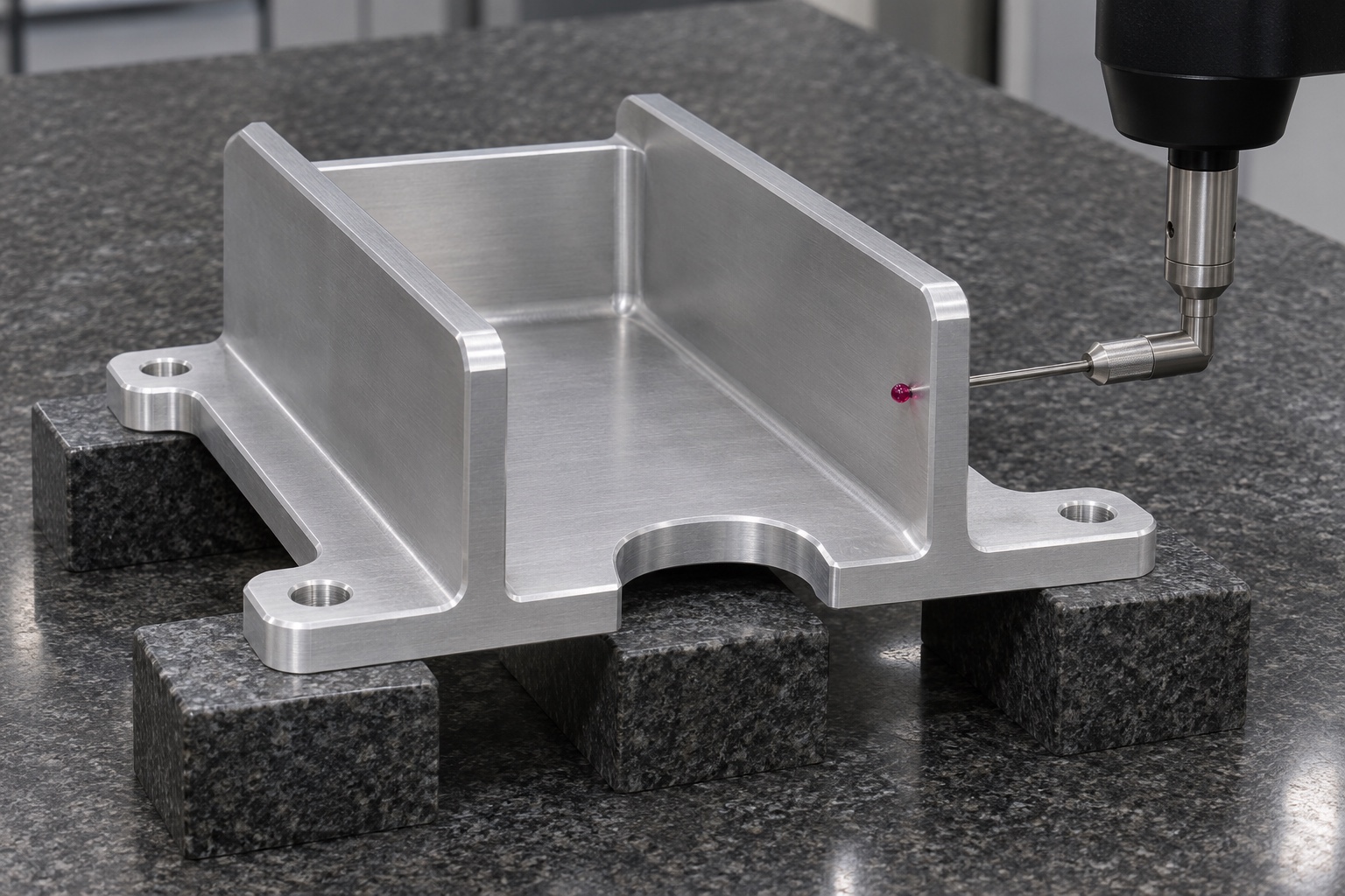
Raised material at cavity transitions, the access opening and mounting holes is removed using an approved method. Finishing should not erase a seating land, thin a defined wall or enlarge an opening without authorization. Features affected by a geometry-changing step need appropriate reinspection. A clean-looking outside does not prove every internal region is free of fragments. Limited inspection access is resolved before production. Ordinary chip removal is not presented as validated medical cleaning or sterile preparation. Any special cleanliness process requires explicit acceptance and evidence, kept separate from the dimensional report for the aluminum guard rather than implied by its polished appearance.
Plan first-article evidence by characteristic
A first-article plan would identify revision, material, final state, support and methods for checking seating, mounting pattern, wall positions and access geometry. Each measurement needs a defined reference and an actual accessible surface. A connector-shaped reference passing through a window cannot verify hole position or base form. A mounting screw trial cannot verify the complete internal clearance. No measured values, tolerance capability or acceptance rates are published in this case. Real reports must be associated with identifiable parts and state limitations or unverified features. That makes the supplier's evidence usable without converting a local observation into a claim of complete detector-interface qualification.
Investigate a hypothetical inert-envelope interference
If agreed, an identified non-electrical connector reference could be compared with the guard under documented orientation and support. No detector, power or radiation source is needed for that geometry check. As a hypothetical review situation, an early stop would prompt checks of entry profile, internal radius, rear clearance, wall state and reference identity. This is not a reported customer incident. The reference is not forced and the walls are not pushed aside merely to obtain a fit. A manufacturing deviation and a design conflict require different approved dispositions. The comparison cannot establish impact resistance, shielding, strain relief, ingress protection or electrical safety.
Protect walls and close the actual order
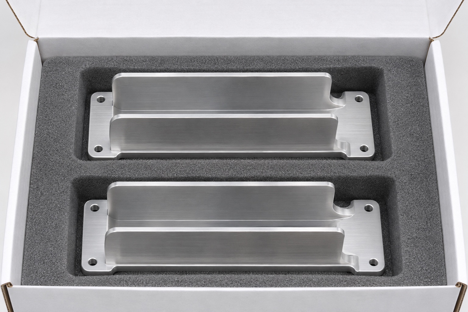
Packaging would separate guards and support the base without distorting side walls. Protective material should not leave fragments in the cavity, opening or fastener features. Revision and material identification remain associated with the components outside functional contacts. Normal protective packaging is not called a sterile barrier. To place a real order, the parties must approve files, quantities, material, finish, inspection scope and delivery protection. This case provides a concrete discussion of medical equipment machining without inventing a customer, completed shipment or qualified protection function. The responsible device organization retains the separate requirements and evidence needed for the complete detector and its intended use.
FAQ
Is this a certified detector protection accessory?
No. It is a representative machining and inspection plan. No customer delivery, protection rating, shielding result or device approval is asserted. A real project needs its own requirements and evidence.
Why distinguish installed envelope from insertion path?
A reference may fit in its final position but collide while being inserted or removed. The approved geometry should identify both spaces where relevant instead of relying only on a front-view opening.
Does a cable opening establish strain relief?
No. Its geometry alone does not prove a restraint or durability function. Cable, routing and any performance requirements must be defined and evaluated separately by the responsible device organization.
Can a guard be accepted while its walls are forced apart?
Not as an arbitrary fit condition. Acceptance follows the specified free or mounted state. The support and hardware must be reproducible and should not conceal an unexplained geometric mismatch.
What would an inert connector comparison establish?
Only observed geometric contact under the recorded setup. It cannot establish impact resistance, shielding, ingress protection, strain relief or electrical safety of the complete interface.
What must be supplied for an actual offer?
Provide matching approved files, alloy condition, quantity, final finish, functional references, connector and adjacent envelopes, access and wall definitions, inspection requirements and protective packaging instructions.

tanghangyun@oemach.com