
Separate the guard from detector performance
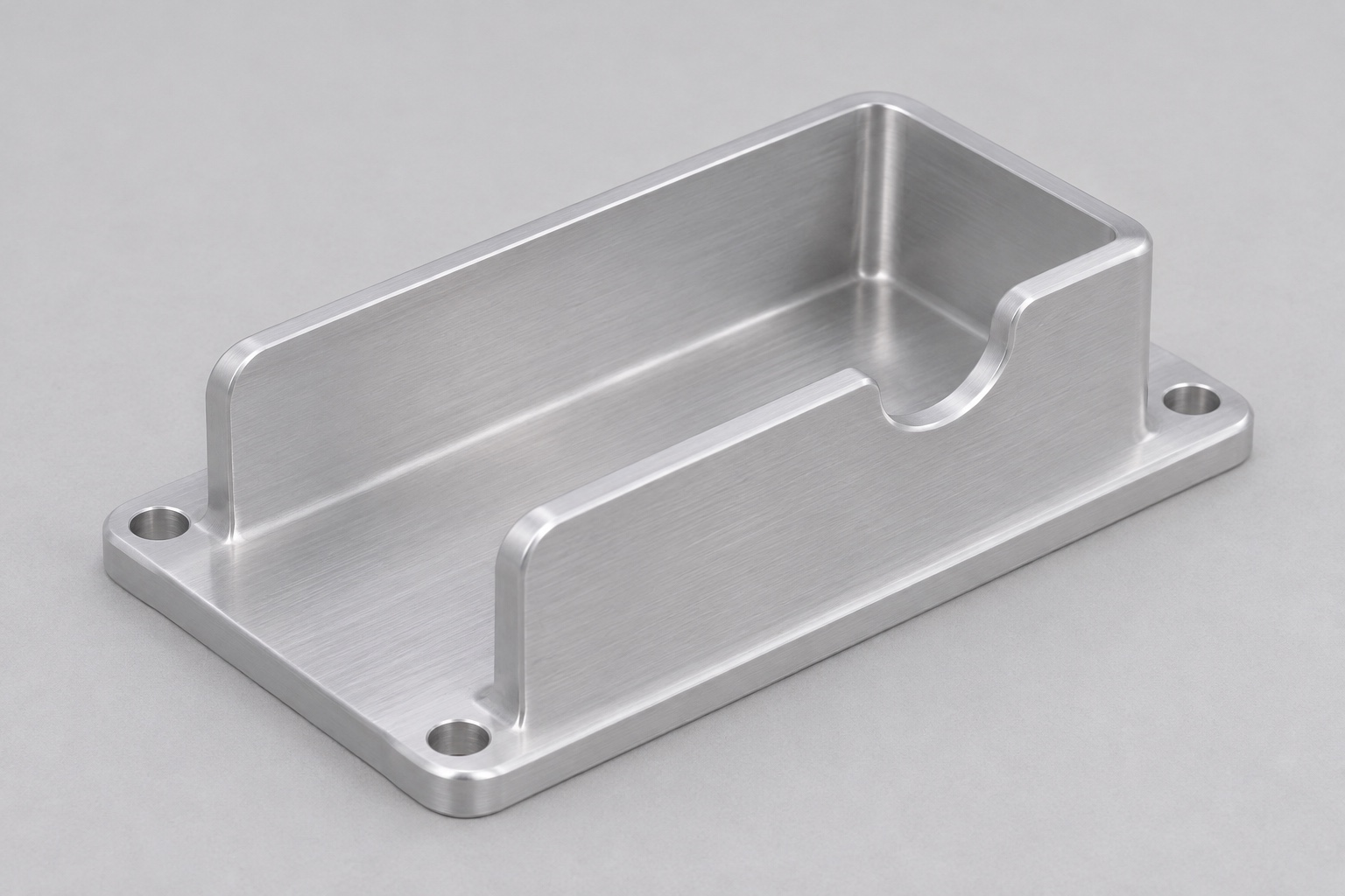
6061 CNC milling for a portable radiography detector connector guard concerns a mechanical housing feature, not the detector's imaging or radiation-control function. A base, side walls and an access opening can surround a separately specified connector envelope. This guide explains how such geometry is defined, manufactured and inspected. It does not establish shielding, electrical safety, impact resistance or an ingress-protection rating. The word guard is not a performance test. The device owner must define intended loads, approved components and any system-level evidence. A machining supplier needs a controlled interface rather than an application name that leaves the actual clearance and acceptance conditions unstated.

Identify the mounting plane and locating features
Determine which base surface seats against the detector housing and what features control lateral position. Relate the internal envelope and mounting holes to those references. An attractive exterior wall is not automatically a functional datum. If only selected lands contact the housing, identify them and distinguish relief regions. The inspection method should recover the same references without requiring a powered detector. This lets a supplier evaluate a standalone component and makes readings comparable across setups. A drawing that relies on an unrecorded assembly to establish its reference is incomplete for repeatable machining and inspection, even if the model appears simple.
Define the connector envelope in three dimensions
Use the approved mechanical envelope of the connector and any relevant retention hardware. A width in the front view does not establish depth or rear clearance. Identify intended contact, prohibited contact and open space. The supplier should not infer those regions from the shape of a commercial plug or a photograph. If another housing part limits access, supply its approved geometry as well. Separate the envelope required for the installed reference from any path needed to insert or remove it. Those are different questions. The machining package should state which geometry is being accepted instead of describing every clearance as a generic connector fit.
Review cable access without inventing cable requirements
An exit notch or window needs a defined location, profile and relationship to the mounted connector. The device designer must specify the actual cable envelope and any routing limits; the machining supplier should not invent a bend radius or strain-relief function. Even an opening that passes an inert reference in one direction may obstruct the approved installation path. Compare the relevant geometry before cutting. Entry radii and edges should follow controlled requirements. The article offers no instruction to modify an operating detector or cable. Its scope is a verifiable component definition that identifies the space the machining process must preserve.
Specify wall sections and corner transitions
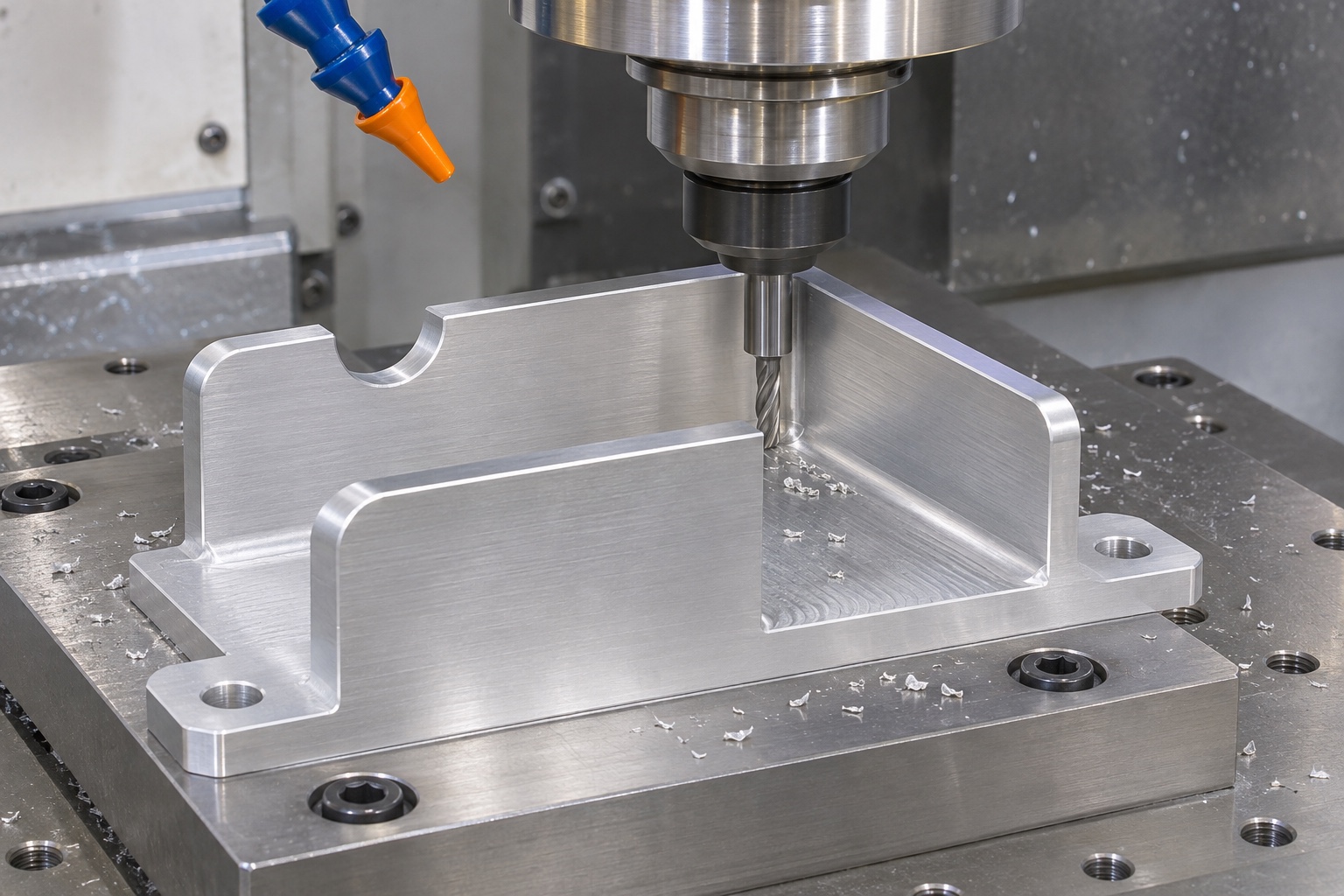
Identify wall height, remaining thickness, local recesses and the transition to the base. Thin or tall walls influence support and tool access, so review them as real sections rather than lines on a drawing. A milling cutter leaves internal radii; compare those radii with the approved connector envelope. Any relief or corner change needs approval if it affects clearance, mounting support or material remaining. Do not enlarge the whole cavity to solve an unidentified local obstruction. Resolve how the final wall and corner geometry will be inspected, especially where a deep pocket or narrow access limits contact with the measurement instrument.
Define alloy condition and final surface state
State the requested 6061 condition, stock form and material-document scope. Another silver-colored alloy is not an automatic substitute. If an external finish is specified, identify masked areas and dimensions that apply after the process. Clearances measured before finishing should not be represented as final-state evidence without checking that requirement. This guide does not claim a friction value, corrosion rating or conductive bond from a coating name. Those questions require separate definition and evidence. Keep the approved finish and material associated with the drawing revision so manufacturing, inspection and purchasing share the same final component state rather than different assumed versions.
Plan machining with the remaining structure supported
The process review considers how removing the internal cavity changes support for the side walls and base. Establish useful reference surfaces and identify how they are recovered after any setup transfer. A route suitable for a solid block may not suit the part after most of that material is removed. Tool approach, reach and chip exit should be reviewed together with the section left behind. No universal feed, speed or cycle time is supplied here. The supplier should explain the chosen sequence for the actual blank and machine, including any later operations that can affect a finished mounting surface or the internal envelope.
Avoid confusing fixture restraint with component form
Workholding should contact permitted regions without forcing thin walls into a temporary shape that is then treated as acceptable geometry. Specify whether inspection occurs in the free state or a defined mounted condition. If the latter is required, reproduce its approved support and hardware rather than choosing convenient clamp force. A base pressed flat in a vise does not prove released flatness. Differences in readings should first prompt review of reference, support and final surface state. The goal is to evaluate the required component condition, not to remove material until one particular fixture yields a favorable result that another inspector cannot reproduce.
Finish openings and preserve functional edges
Remove raised material at the access window, cavity transitions and mounting holes using an agreed method. Edge finishing must not shorten a support land, reduce a specified wall or alter the usable connector opening without authorization. Inspect affected geometry after any operation capable of changing it. A smooth exterior does not establish that the inside contains no loose fragments. Resolve difficult access before production. Ordinary chip removal is not a validated medical cleaning process, and a protective package is not automatically a sterile barrier. Special cleanliness or residue requirements should be specified separately, with evidence distinct from the dimensional inspection report.
Inspect the envelope and mounting pattern separately
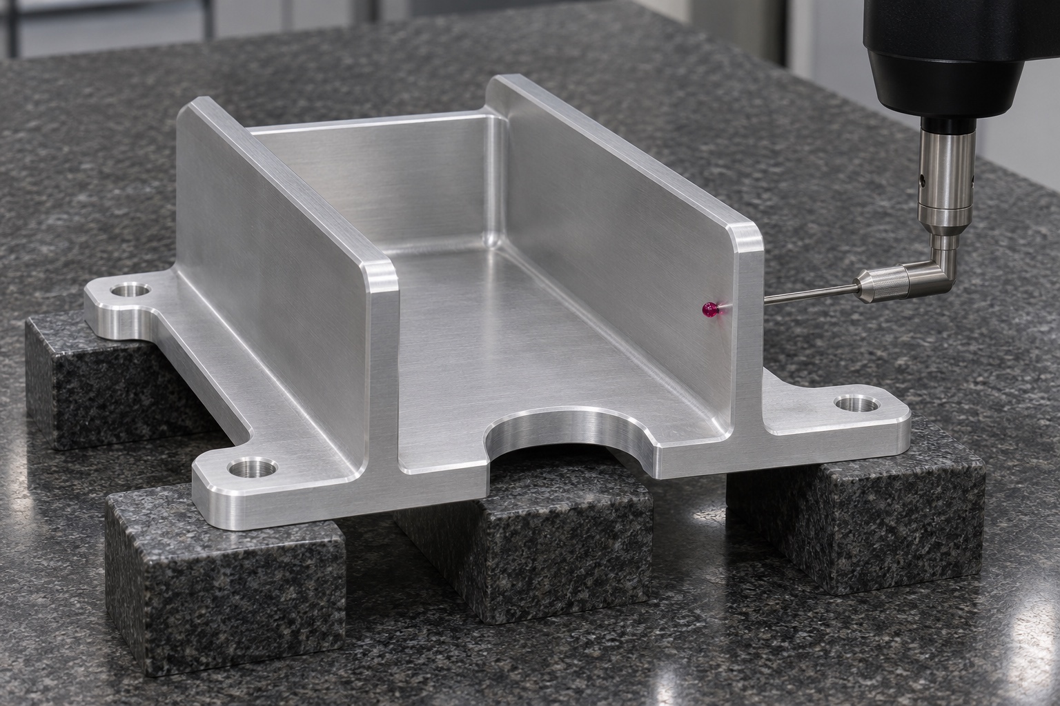
The inspection plan should evaluate base seating, hole pattern, internal wall positions and access profile in their specified relationships. A plug-shaped reference passing through an opening cannot verify the complete mounting pattern. Likewise, a mounting screw fitting does not establish the internal clearance. Choose methods for the actual accessible surfaces and document the datum scheme and support condition. Coordinate or optical methods may be considered, but they still require defined characteristics. This article provides no invented tolerances or measured results. Real acceptance values and evidence must come from an approved project and identifiable parts, including explicit limitations of each selected method.
Use an inert envelope for a limited comparison
An identified non-electrical connector reference can help locate interference without a detector, power or radiation source. Record its geometry, mounting reference and insertion direction. Do not force an unexplained fit. The observation concerns only the local geometry under that setup. It cannot establish cable strain relief, connector durability, impact protection, shielding, ingress protection or device safety. Those need separate evaluation. If the reference fits only when a wall is pushed aside, investigate the specified state and the cause rather than accepting that forced fit. Preserve the initial observation before authorizing any correction to the opening or wall section.
Protect the guard and prepare an actionable RFQ
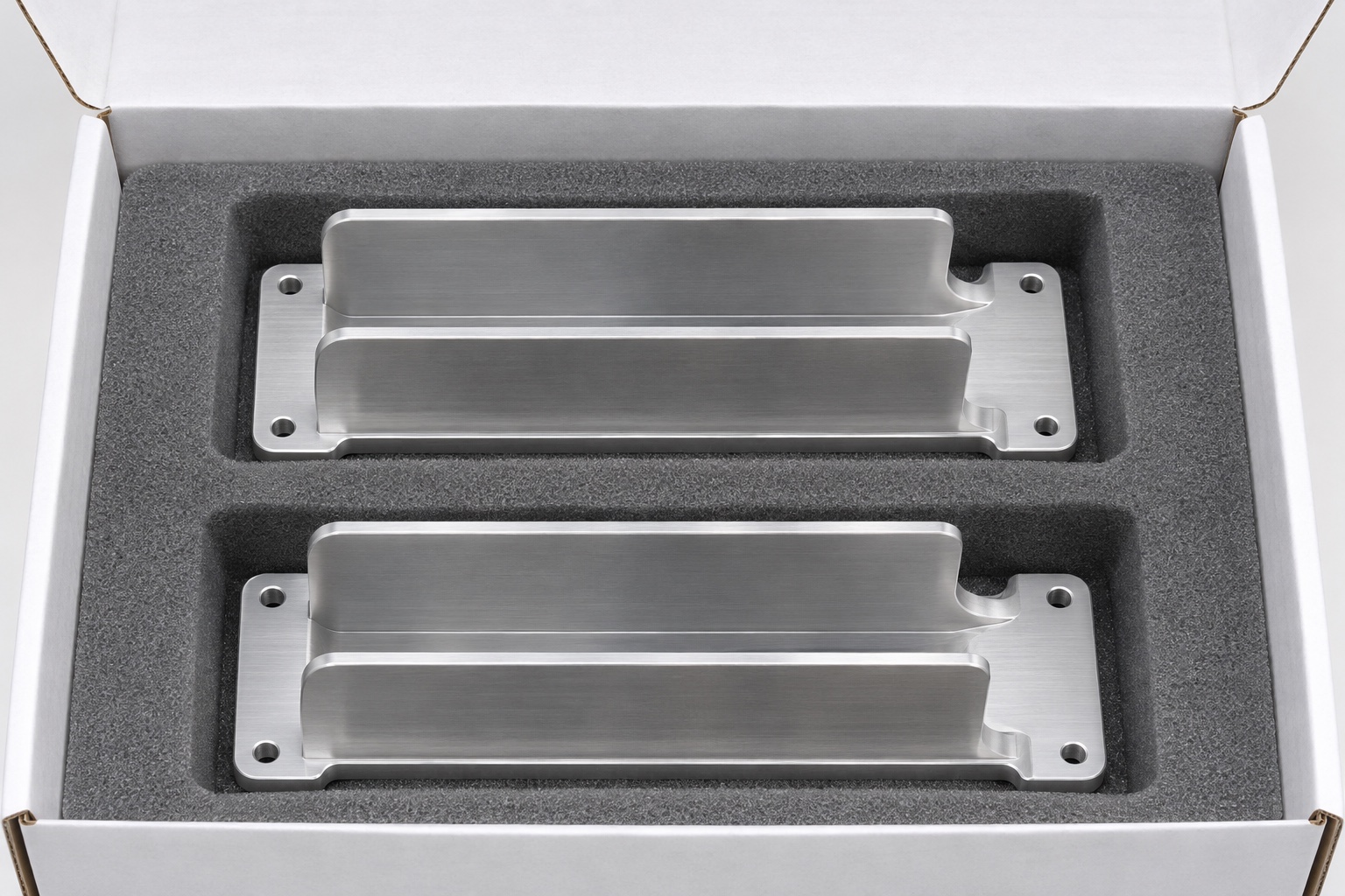
Package guards separately and support the base without spreading or squeezing side walls. Avoid fragments in the cavity, window or fastener features. Maintain material and revision identity outside working contacts. A complete inquiry includes matching model and drawing, alloy condition, quantity, final finish, reference scheme, connector envelope, access requirements, wall definitions, inspection scope and packaging instructions. Supply approved adjacent geometry where it governs space. This gives a medical equipment machining supplier a defined component to quote. It leaves the complete radiography detector and all claimed protection or electrical performance with the responsible organization and its separate evaluation process.
FAQ
Does the word guard imply radiation shielding?
No. This is a mechanical component description. Radiation-related performance, electrical safety and other system functions require separate approved requirements and evidence and are not established by its shape or material.
Is the front opening enough to define connector clearance?
No. Depth, rear features, retention hardware and any insertion path can also matter. Provide the approved three-dimensional envelope and identify which areas require contact or clearance.
Can the supplier choose cable bend limits from experience?
Not as an unstated requirement. The device owner must define the cable and routing conditions. The machining drawing should describe the opening and the approved space it must preserve.
Why inspect the guard in a defined support state?
Clamps or mounting hardware can influence thin walls and the base. Acceptance follows the specified free or mounted condition, not arbitrary pressure used to make a reference fit.
Does an inert connector trial prove protection performance?
No. It provides a limited geometric observation. It cannot establish strain relief, impact resistance, ingress protection, shielding, electrical safety or durability of the complete detector interface.
What information supports a comparable quotation?
Provide controlled files and revision, 6061 condition, quantity, final finish, references, connector and adjacent envelopes, access and wall requirements, inspection evidence and protective packaging conditions.

tanghangyun@oemach.com