
Treat the sleeve as a specified component
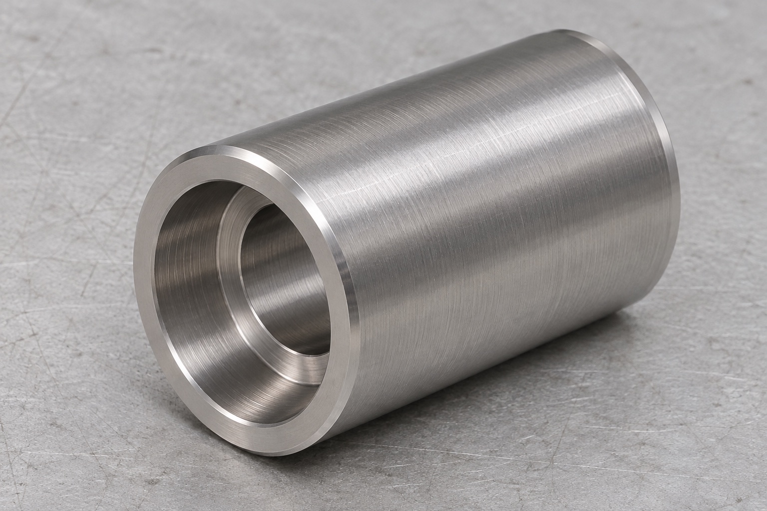
316L CNC turning of a dental handpiece spindle spacer sleeve concerns a mechanical component made to an approved definition. The representative shape is a short tubular body with a stepped through bore and annular end faces. Its application name does not establish interchangeability with a commercial handpiece. This guide explains manufacturing questions and dimensional checks, not how to repair or modify a dental instrument. It does not select a bearing arrangement, preload, operating speed or cleaning cycle. Those requirements belong to the responsible device design. The supplier needs the actual interfaces and acceptance conditions before the sleeve can be quoted as a verifiable machined part.

Identify which bore region locates
Separate the functional locating length from entry chamfers, counterbores and reliefs. A sleeve can contain more than one internal diameter, but they need not all locate on the same mating part. The drawing should identify the working axis and say how it is recovered during inspection. Do not use the outside diameter automatically if the bore governs assembly position. If an adjacent component determines the reference, supply its approved geometry or a defined measurement reference. Establishing that relationship early makes later readings comparable and prevents an apparently correct outside cylinder from concealing an incorrectly related internal feature.
Define the internal step and shoulder
An internal shoulder needs a position, useful contact band and clear relationship to the reference bore. Total cavity depth alone does not describe whether the mating reference reaches the intended face. Specify any allowed corner radius or relief at the change in diameter. A turning tool leaves a corner condition related to its geometry, so an ideal sharp corner in a model must not be assumed manufacturable without review. Keep the useful shoulder separate from the relieved region in the inspection plan. Otherwise, a probe or reference may contact a transition and generate a depth reading that does not represent the intended axial seat.
Relate both end faces to the same definition
Overall length, shoulder position and the distance between working end faces are different characteristics. Identify which face establishes axial location and which relationships must be checked to the working axis. A length reading across two convenient points cannot verify every required face orientation. Also distinguish full annular faces from limited contact bands. If the mating stack uses another reference surface, that information should be explicit. A supplier should not infer an assembly stack from a photograph of a tube. Consistent references let manufacturing and inspection discuss the same functional geometry even when the part is measured in separate setups.

Confirm material and the final acceptance state
The requested 316L designation, stock form and material-document scope must be stated. This guide does not recommend substituting 316L into an existing instrument or treating another stainless grade as equivalent. Define any approved surface treatment or special cleaning process separately, including dimensions that apply afterward. A bright surface is not evidence of alloy identity, biocompatibility or a validated cleaning condition. Keep the final state linked to the controlled drawing revision. Without that link, measurements made before and after a later operation may be compared as though the component had not changed, making an apparent disagreement difficult to interpret.
Plan turning around accessible reference surfaces
The process review considers how to generate accessible bores, shoulders and exterior surfaces while supporting the remaining tubular section. The actual route depends on diameter, length, blank and equipment; no universal feeds or speeds are proposed. Identify which relationships can be established together and which require transfer. If the sleeve is reversed to finish the second end, describe how the working reference is recovered without damaging it. A process with fewer setups can simplify transfer, but it does not automatically prove conformity. The plan still needs appropriate checks after operations that can alter a finished bore or face.
Avoid using clamping to create the measured form
Review the gripping length, contact area and remaining wall before choosing jaws or a collet. A tubular section can be influenced by the way it is held. A reading taken while constrained may not describe the released component. The drawing and inspection plan should identify the required condition rather than allowing arbitrary clamp pressure to define acceptance. Where a specified assembly condition is required, reproduce its approved details separately from ordinary machining workholding. Differences between readings should prompt a support and reference review first. Do not immediately remove additional material simply because one fixture produces a different result from another.
Finish bore entries without erasing useful geometry
Remove raised material at the bore entrances, end faces and internal transition using an agreed method. The allowed edge condition must not shorten the locating length or remove a shoulder contact band unexpectedly. Inspect affected features after finishing steps capable of changing dimensions. A smooth entry does not prove that the deeper shoulder is acceptable. Resolve access for internal inspection before production rather than treating a passing reference shaft as proof of every unseen surface. Ordinary chip removal is distinct from any special cleanliness requirement. Neither a polished appearance nor a closed bag establishes sterile delivery or qualification for a dental procedure.
Select measurements for the actual characteristics
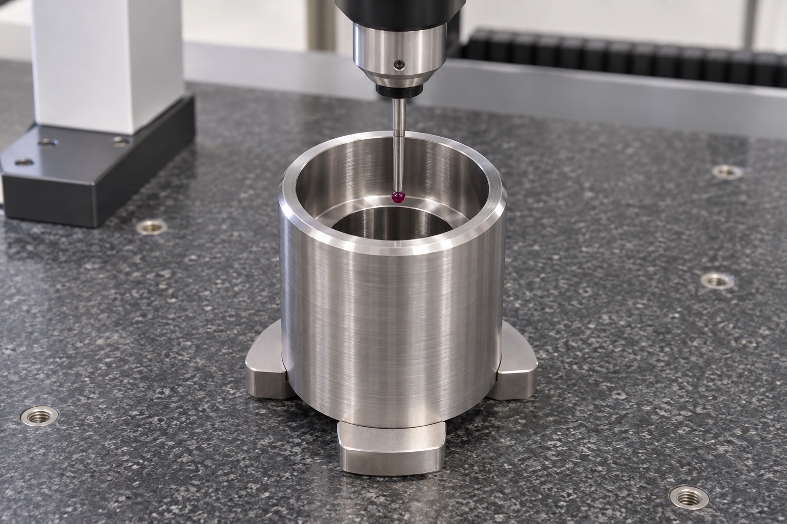
An inspection plan should distinguish bore size, step depth, shoulder location, end-face relationships and any specified exterior geometry. Select instruments according to access and the characteristic being checked. A local diameter measurement does not establish the relationship between two bore regions. A depth check needs a defined starting face and contact region. Coordinate, optical or other approved methods still require an identified reference scheme. Record revision and final state, and state what the method does not cover. This article publishes no invented tolerances or measurements; real acceptance values must come from approved requirements and actual evidence for identified parts.
Use an inert comparison only for geometry
An identified inert shaft or stepped reference can help locate contact without operating a handpiece or using a clinical instrument. Record the reference geometry, support and insertion direction. Do not force the reference past an unexplained obstruction. A dry fit can indicate a local clearance or seating condition, but it does not establish bearing preload, balance, rotational performance or instrument life. Those questions need separate approved evaluation. Keep the reference identity with the observation so another trial is not called equivalent after a different shaft or support has been substituted. The scope of the comparison should remain clear in every report.
Diagnose an early stop before changing the bore
If a reference stops before the expected shoulder, review entry edges, internal corner condition, usable length, reference alignment and drawing interpretation. Enlarging all bores could hide a local obstruction while changing the intended locating fit. Preserve the original observation before corrective work. A manufacturing deviation requires an approved disposition; an incomplete or conflicting design needs clarification or revision. The symptoms may initially look the same, but the decisions are different. Repeat inspection of affected features after any authorized correction. The goal is a reproducible component against controlled requirements, not one sample that fits after undocumented hand finishing.
Protect the sleeve and prepare the request
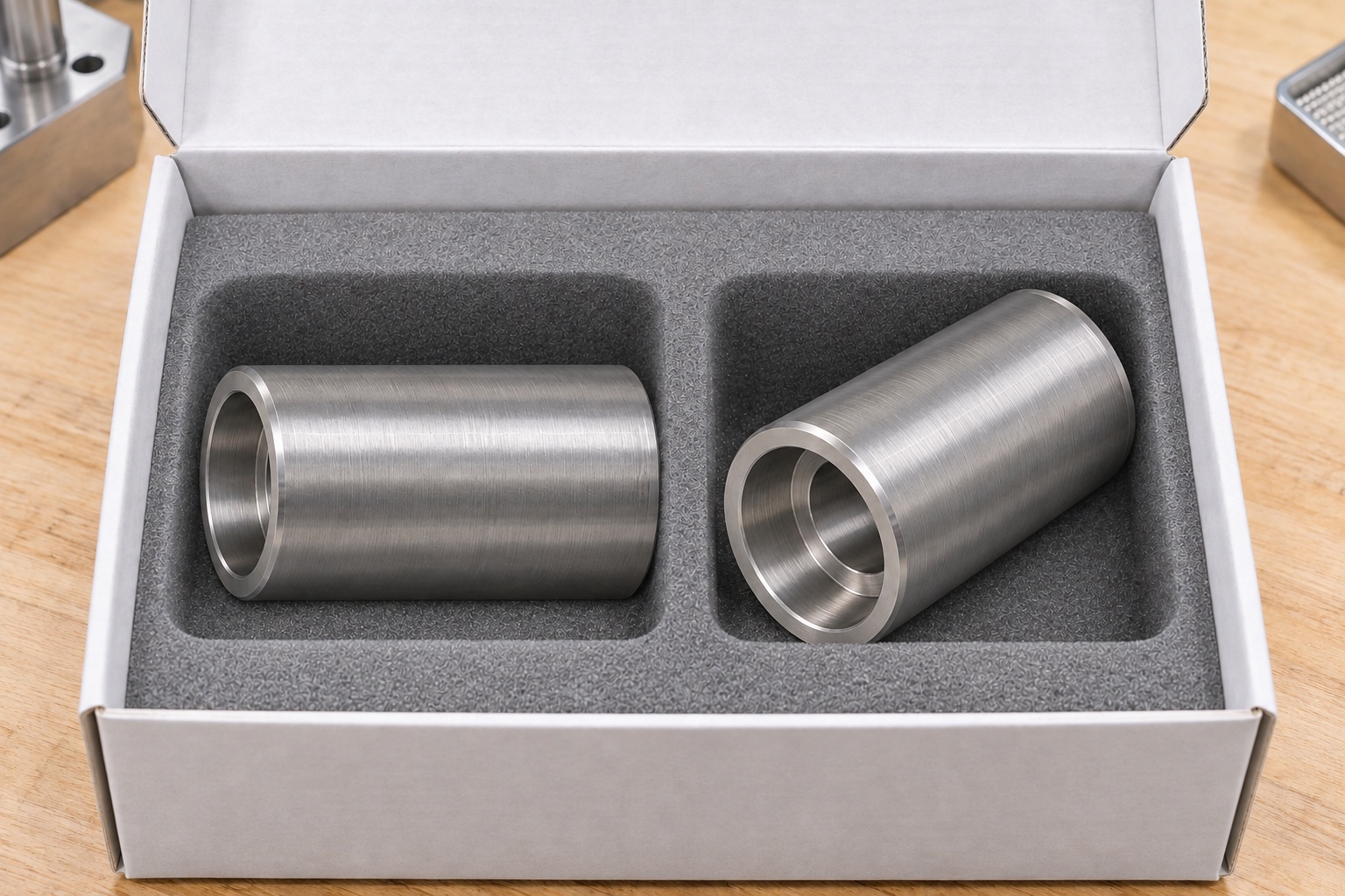
Separate sleeves in transport so annular faces and bore entries do not strike other metal parts. Packaging support should not distort a tubular section or leave fragments inside the stepped bore. Keep revision, material and inspection records associated with the parts outside working contacts. A complete RFQ includes consistent model and drawing, material specification, quantity, final state, reference scheme, internal-step details, face relationships, inspection evidence and packaging requirements. Add approved mating geometry where it governs contact. This allows a precision medical machining supplier to quote a defined sleeve while leaving the operating and clinical qualification of the complete handpiece with the responsible organization.
FAQ
Does a correct outside diameter prove the sleeve is concentric?
No. Identify the functional bore reference and the required relationships. An outside size reading cannot establish the position or alignment of internal steps and shoulders.
Is total length enough to define the axial interfaces?
No. The usable end faces, internal shoulder and their relationships need separate definition. A single overall length does not describe every contact in a mating stack.
Can an internal shoulder corner be assumed perfectly sharp?
No. Review the turning-tool geometry and any permitted relief or radius. The drawing must distinguish the usable contact band from the transition region before manufacturing and inspection.
Should the part always be measured in a collet?
Not automatically. Acceptance follows the specified state and reference system. Workholding can affect a tubular section, so constrained and released readings should not be treated as equivalent without review.
Does an inert shaft fit qualify a dental handpiece?
No. It provides only a limited geometric observation. It does not establish preload, balance, speed capability, service life, cleaning validation or suitability for clinical operation.
What should the buyer send for quotation?
Provide approved files and revision, material, quantity, final finish, datum scheme, bore-step and face definitions, inspection requirements and packaging instructions, plus mating geometry where needed.

tanghangyun@oemach.com