
A representative plan rather than a delivery claim
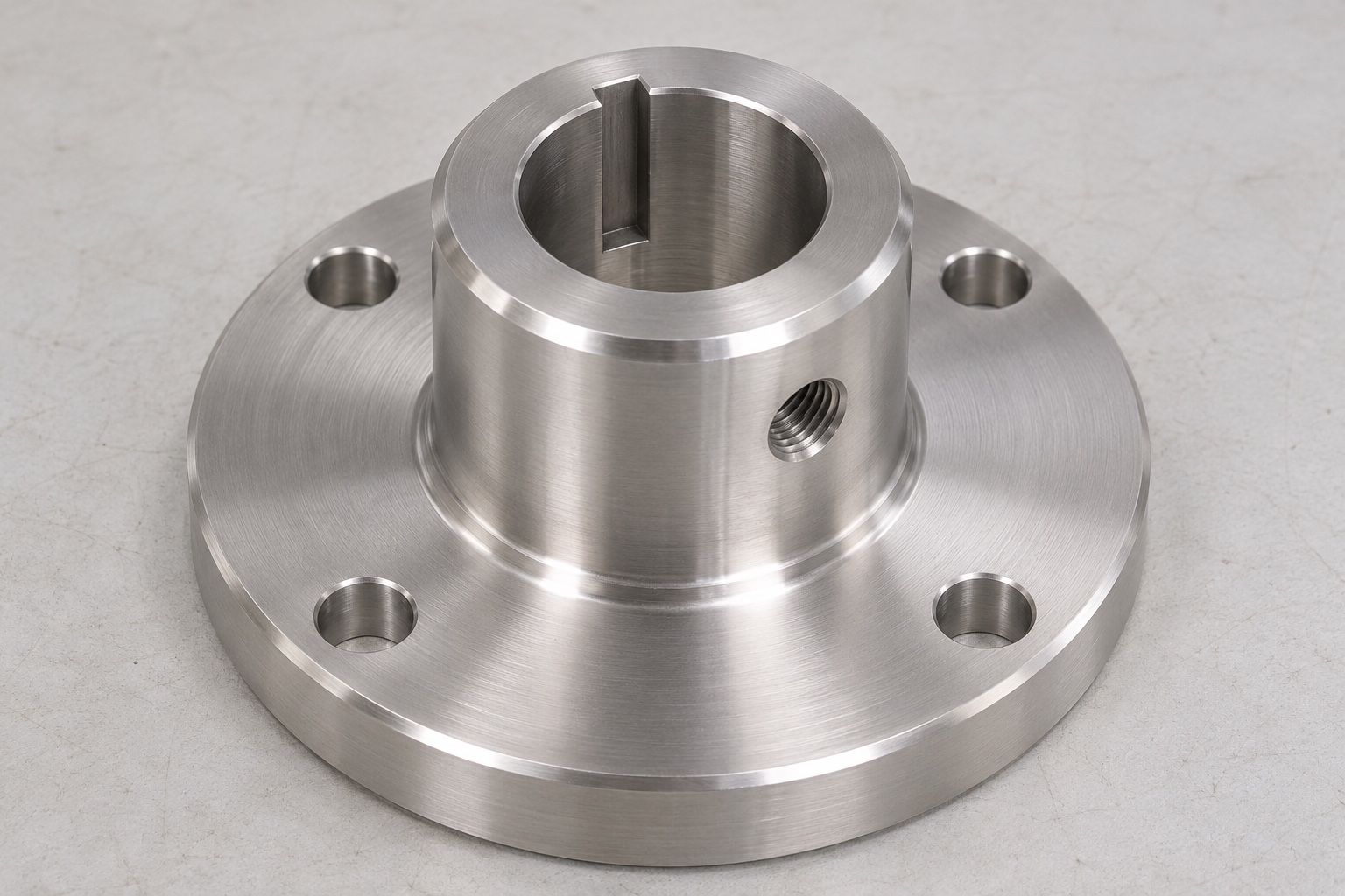
This medical CNC machining case describes a representative 316L reagent carousel drive hub for an analyzer mechanism. It is not an account of an identified customer order, completed shipment or validated instrument. No certification, inspection result, operating torque or assay performance is claimed. The purpose is to explain the decisions needed to manufacture and inspect a mechanical interface from controlled requirements. The proposed route considers a bore, an internal keyway, a seating flange, mounting holes and a radial thread. Every dimension and acceptance criterion for a real project must come from the approved drawing and an agreed inspection plan.

Separate the hub's locating and fastening functions
The considered geometry has a short cylindrical boss on a circular flange. A central bore locates against a specified shaft, while an internal keyway can provide an angular relationship. Flange holes connect to a separately defined structure. A radial threaded feature is another interface, not automatic proof of a particular retention scheme. The drawing must say which surfaces locate, seat or provide clearance. A large external diameter may be convenient to hold but need not be the functional reference. Keeping those roles distinct prevents the supplier from accepting a collection of correct individual dimensions while missing the relationships that the assembled mechanism requires.
Establish the real quotation inputs
A real inquiry would supply matching model and drawing revisions, the requested 316L material specification, stock or document requirements, quantity and final surface condition. Mating shaft, key and flange information is useful when it defines contact or clearance. A photograph and a nominal shaft size cannot establish the entire interface. The buyer should identify which inspections are required and which assembly evaluations remain outside the machining order. Any external finishing step belongs in the scope before quotation. This allows suppliers to compare the same work instead of silently adding different assumptions about keyway ends, thread engagement or the intended operating conditions of a medical analyzer.
Review the keyway route before committing stock
The keyway needs a defined width, depth convention, useful length and termination. The representative planning step compares those requirements with access for a proposed cutting route. Through and blind constructions can require different approaches, so the route is not selected only from the word keyway. If a local relief or end modification is proposed, the design owner must approve it. The change must not remove an intended locating or driving contact. Updated model and drawing revisions should agree before manufacturing starts. This review is a planning example and does not assert that a particular broach, slotting tool or machining center has already produced acceptable parts.
Preserve the identity of stainless material
For an actual order, incoming material would be checked against the requested designation and documentary scope. Similar appearance is not evidence that two stainless grades are interchangeable. Required material identity should remain associated with the parts through cutting, turning and later operations. Any treatment or special cleaning requirement needs its own approved specification and final acceptance state. This case does not present a material certificate or claim reagent compatibility. Its contribution is to show where those requirements enter the project and how they would be traced. The word medical should not be used to imply that an ordinary turned component carries approvals never requested or verified.
Turn the main reference geometry coherently
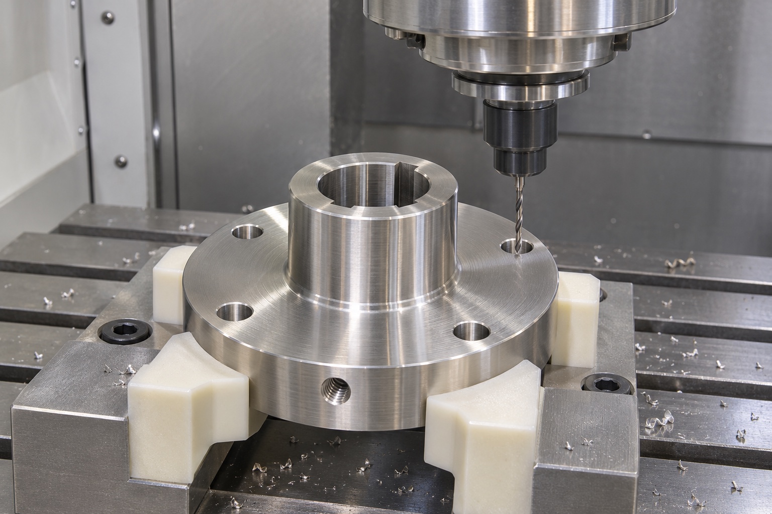
The proposed turning review considers the bore, boss and flange face together, including support and tool access for the actual blank. Holding surfaces should not damage the finished locating region. The plan identifies which geometry is completed in a shared setup and what must be recovered after transfer. No production time, cutting speed or universal capability is invented for this example. A suitable sequence depends on size, remaining section and equipment. Before moving to secondary features, the supplier should be able to explain how the working axis and axial seating face will be reconstructed. That continuity matters more than simply reducing the number of operations on a process sheet.
Locate the flange pattern and radial feature
The flange holes and radial threaded feature are positioned according to the approved bore and angular references. The planning review checks access for drilling, threading, exit finishing and later inspection. If the radial hole intersects the bore or keyway, its actual location must be explicit. A hole with the right diameter or thread can still be wrongly positioned. Likewise, an evenly spaced flange pattern may be rotated relative to its intended angular origin. The process plan should distinguish these relationships instead of treating a successful tool cycle as acceptance. Any proposed fixture needs an identifiable method to recover both the axis and the required clocking.
Finish accessible and internal edges deliberately
Raised edges at the bore mouth, keyway, flange holes and radial feature need an agreed finishing method. Removing a burr must not change useful keyway faces or shorten the locating bore unexpectedly. The plan includes inspection of affected regions after finishing, especially at an internal intersection. A clean-looking outer surface is not proof that every internal edge is acceptable. If direct access is limited, the method is resolved before the order proceeds. This case does not equate ordinary chip removal with validated cleanliness or sterile delivery. Such requirements would need a separately specified process and evidence, rather than a general instruction to make the hub look polished.
Plan first-article evidence around relationships
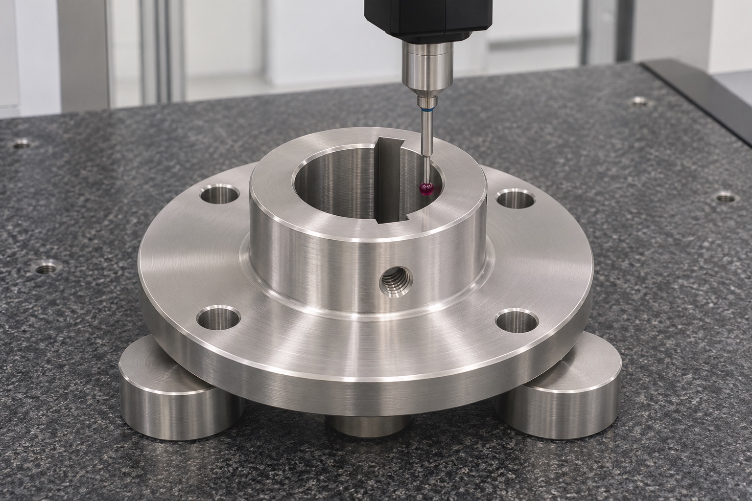
A first-article plan would record the controlled revision, material identity, final surface state and inspection method. The locating bore, flange face, keyway and mounting pattern are evaluated through the same defined references. Keyway size and its angular relation are separate questions. A thread check is not a substitute for checking the radial hole's position. This representative case publishes no numeric results, tolerance capability or acceptance percentage. A real report must contain evidence from identified parts and state any unverified characteristics. That distinction helps the buyer understand what the machining supplier has actually confirmed and what still belongs to a separate assembly review.
Use identified inert references for a limited comparison
If agreed, a dry bench comparison could use an identified shaft, key and flange reference without reagents or an operating analyzer. The setup records orientation, support and contact location. It should not use force to overcome unexplained interference. A matching fit can support a narrow geometric observation but cannot establish carousel balance, torque capacity, indexing reliability or analytical performance. Those claims require separate system evidence. The comparison record needs the identities of its references so another check can reproduce the same condition. Substituting a different shaft later should not be presented as an equivalent trial without reviewing its geometry and state.
Treat an early stop as a diagnostic example
As a hypothetical review situation, a reference shaft might stop before the hub reaches its intended seating face. The investigation would compare bore entry, keyway end, reference alignment, raised material and the specified clearance. This is not a reported customer incident. The original contact observation should be preserved before any corrective cutting. A manufacturing deviation requires documented disposition; an incomplete or conflicting design needs an approved revision. Neither should be hidden by enlarging the bore until a sample happens to fit. Separating those causes preserves a repeatable interface for later parts and makes the reason for any correction available to the next inspector.
Protect the interface and close the real project scope
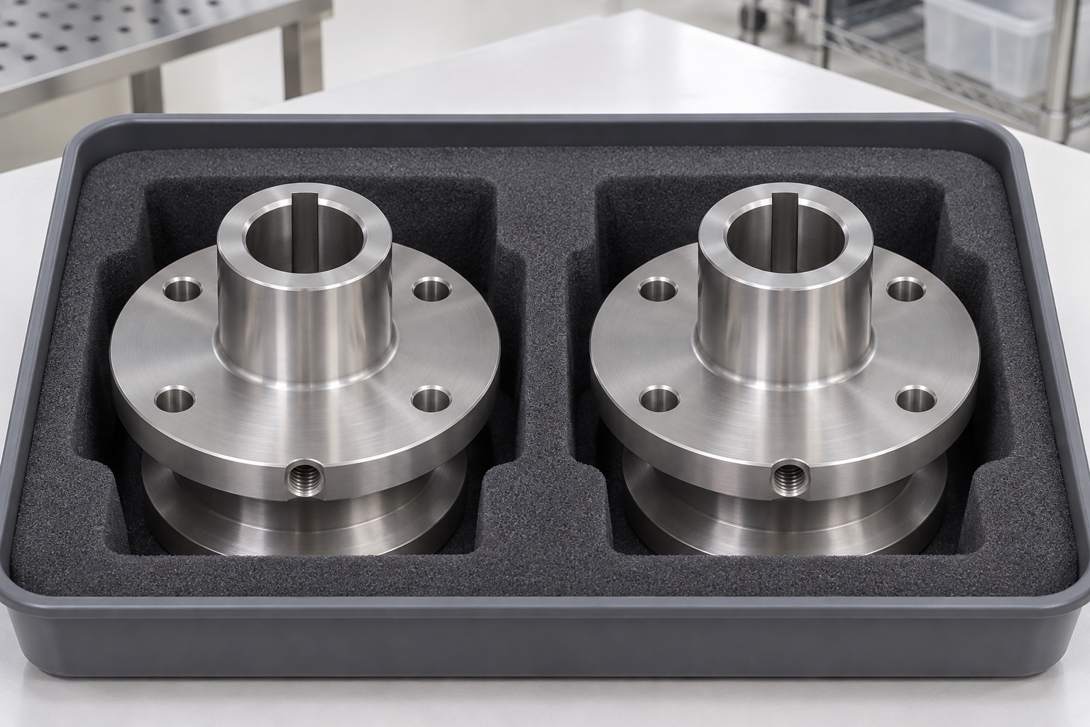
The proposed packaging keeps hubs apart and protects flange faces, bore entries and finished boss surfaces. Packaging contacts should not introduce fragments into the keyway or radial thread. Identification remains associated with revision and material records outside functional contact regions. Ordinary protective packing is not called a sterile barrier. To convert this example into an actual project, the parties must approve files, quantities, material, final finish, inspection evidence and delivery conditions. The case offers a concrete route for that discussion without inventing customers, production outcomes or device approval. Any later analyzer evaluation remains with the organization responsible for the complete instrument and its intended use.
FAQ
Is this an account of a completed analyzer hub delivery?
No. It is a representative manufacturing and inspection plan. No customer, finished order, certification or acceptance result is asserted. Real projects need their own approved documents and traceable evidence.
What distinguishes locating features from fastening features?
The drawing assigns each surface its role. The bore and flange face may locate and seat, while holes serve specified connections. Do not infer all those functions solely from the shape shown in an image.
Why review the keyway termination early?
Its useful length and end condition affect tool access and mating clearance. Any proposed relief or route change needs approval before it is incorporated into the model, drawing or process plan.
Does a correct radial thread confirm retention performance?
No. Thread size and position are manufacturing characteristics. Screw-tip contact, retention force and permissible operating torque require separately defined assembly conditions and evidence, not a passing thread check alone.
What would an inert shaft comparison demonstrate?
Only the observed geometric fit under the recorded setup. It cannot demonstrate dynamic balance, analyzer indexing, reagent handling or assay accuracy. Those evaluations are outside this machining example.
What is needed before requesting a real offer?
Provide consistent drawing and model revisions, material and finish requirements, quantity, reference scheme, keyway and thread definitions, inspection scope and packaging conditions, plus mating geometry where it governs the interface.

tanghangyun@oemach.com