
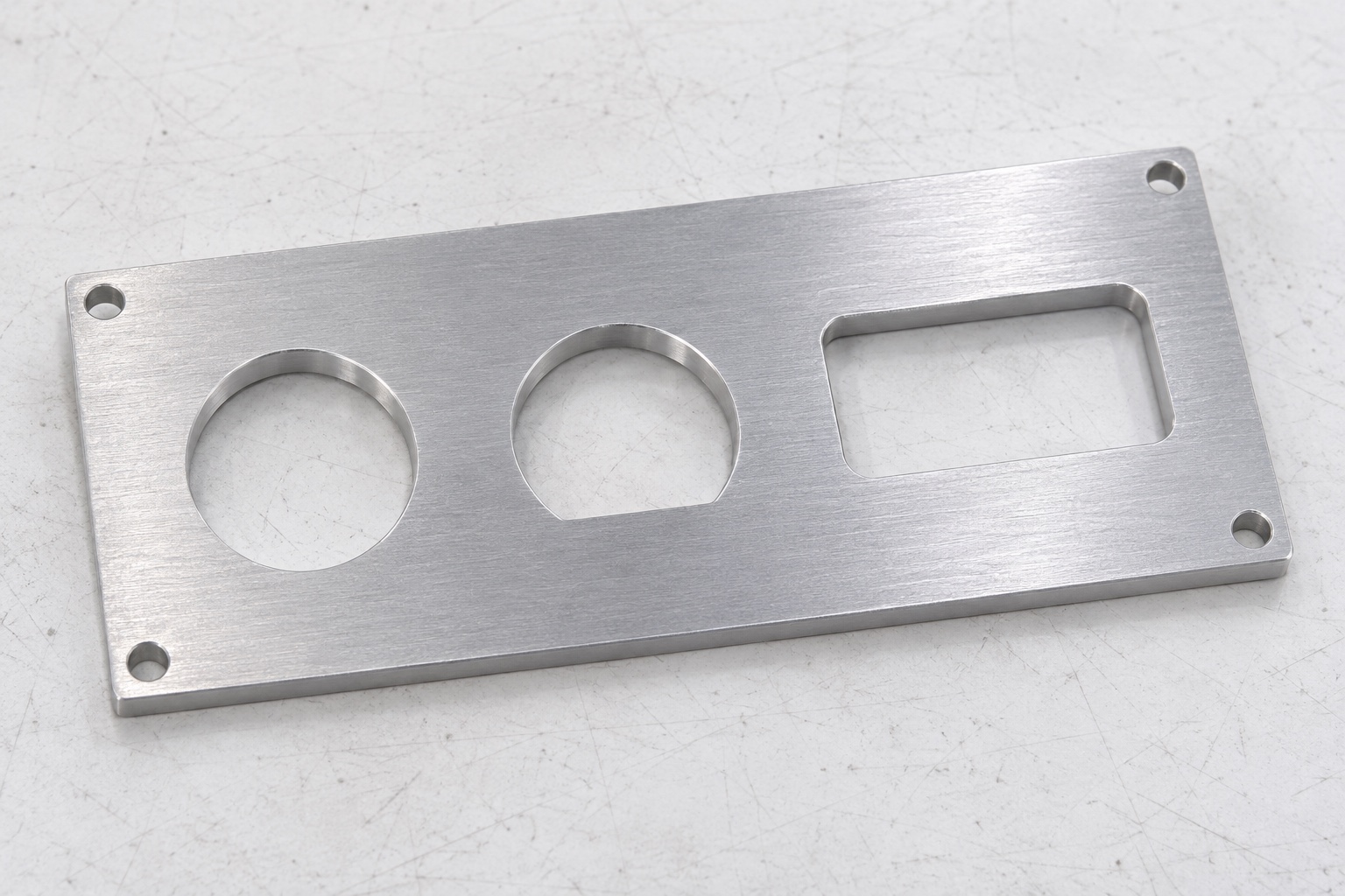
Separate the panel from the audio instrument
6061 CNC milling of a portable audiometer connector panel addresses a mechanical interface in diagnostic equipment. The panel may carry circular openings, an anti-rotation flat, a rectangular window and fastening features. This guide considers how those features can be defined, machined and inspected. It does not establish acoustic calibration, signal quality, electrical safety or compatibility with a named audiometer. A correct mechanical panel is only one part of a complete approved instrument. Begin with the controlled component drawing and the separately defined connector envelopes rather than inferring interface requirements from a photograph or assuming that a connector entering a hole proves the system is ready to use.

Define the viewing direction and mounting references
Identify which face is outside the enclosure and how the panel locates on its support. A drawing should make front and rear views unambiguous, particularly when an opening has an angular key or an asymmetric mounting pattern. Define the relevant seating face, edge or locating feature in the datum structure. Screw clearance holes are not automatically precise locating references. The inspector needs to reproduce the intended orientation without guessing how a mirrored layout is meant to assemble. Record which characteristics refer to the front surface and which apply at the rear, so a correct-looking pattern is not accepted in the wrong handed condition.
Specify each connector opening by its useful geometry
Separate the cylindrical region, anti-rotation flat, entry and any local relief. A nominal hole diameter alone does not define a keyed interface. Identify the useful wall thickness over which the flat and curved surfaces apply. For a rectangular opening, specify corner conditions consistent with the actual manufacturing route and mating envelope. Do not quietly widen every opening to make a generic sample fit. The model and drawing must describe the same interface. The supplier should know which regions locate the connector, which provide clearance and which are expected to be inspected independently rather than accepted through an uncontrolled assembly trial.
Review the complete rear envelope
The connector's visible flange is not its complete mechanical envelope. A rear body, retention feature, fastening hardware or cable clearance can interfere even when the panel opening is correct. Obtain the approved mating geometry and identify the region that belongs in the component or assembly check. Do not infer cable routing or connector identity from an image. The machining supplier is not automatically responsible for an entire wiring assembly. A clear request distinguishes the cutout dimensions it must manufacture from the rear-envelope conditions that a defined inert mock assembly will evaluate. This makes a fit observation interpretable without creating a claim about the electrical function.
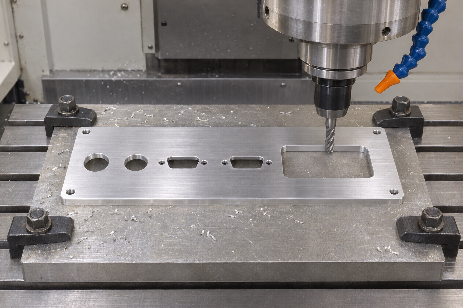
Specify alloy, temper and final finish state
Identify the 6061 material condition and stock form, together with required documentation. If anodizing or another finish is specified, state which dimensions apply afterward and which interfaces require protection or a defined final condition. A chosen color does not establish electromagnetic performance, corrosion suitability or electrical bonding. Those requirements must come from the actual design and have appropriate evidence. The supplier should not invent them because the part belongs to medical equipment. Finish and marking requirements also need a permitted location so they do not alter a connector seat or obscure the part identity needed to connect it with the inspection record.
Plan the panel's support during pocketing and cutout milling
A thin panel can be held flat by a fixture while its free-state geometry differs. Review support locations, clamp forces and the changes in stiffness as openings are produced. The route should preserve mounting references and allow tool access without loading a narrow web between cutouts. Consider the exit side of through-features and how the part is protected when reversed. No universal cutter or cutting parameters are prescribed here. The actual geometry and stock determine the appropriate route. The process sheet should explain how it preserves the specified relationships, not simply list a sequence of holes whose positional reference is unclear.
Control angular flats and internal corners
The flat of a keyed circular opening has a position and angle relative to the mounting reference. Review how it will be finished and measured, including any transition radius. A rotating cutter leaves an internal radius at a rectangular corner; the design must permit that geometry or define another approved route. Do not remove a functional flat or change the orientation to accommodate an unreviewed tool. Each opening should remain tied to the same drawing intent. A plug or connector sample can clear one part of an opening and bind on another, so the useful flat and curved regions need separate attention in the inspection plan.
Finish entry and exit edges without losing interface length
Deburring must remove prohibited raised material while preserving panel thickness, useful wall geometry and the specified seating face. A large hand-finished chamfer can shorten the anti-rotation engagement or change the apparent location where a flange seats. Define allowed edge conditions on the drawing and inspect after the operation that produces them. Both sides matter on a through-opening. Where a region is difficult to reach, resolve the access and verification method before acceptance. A smooth front face does not establish the rear condition. Avoid treating a successful connector insertion as proof that all edges, steps and faces meet their separate requirements.
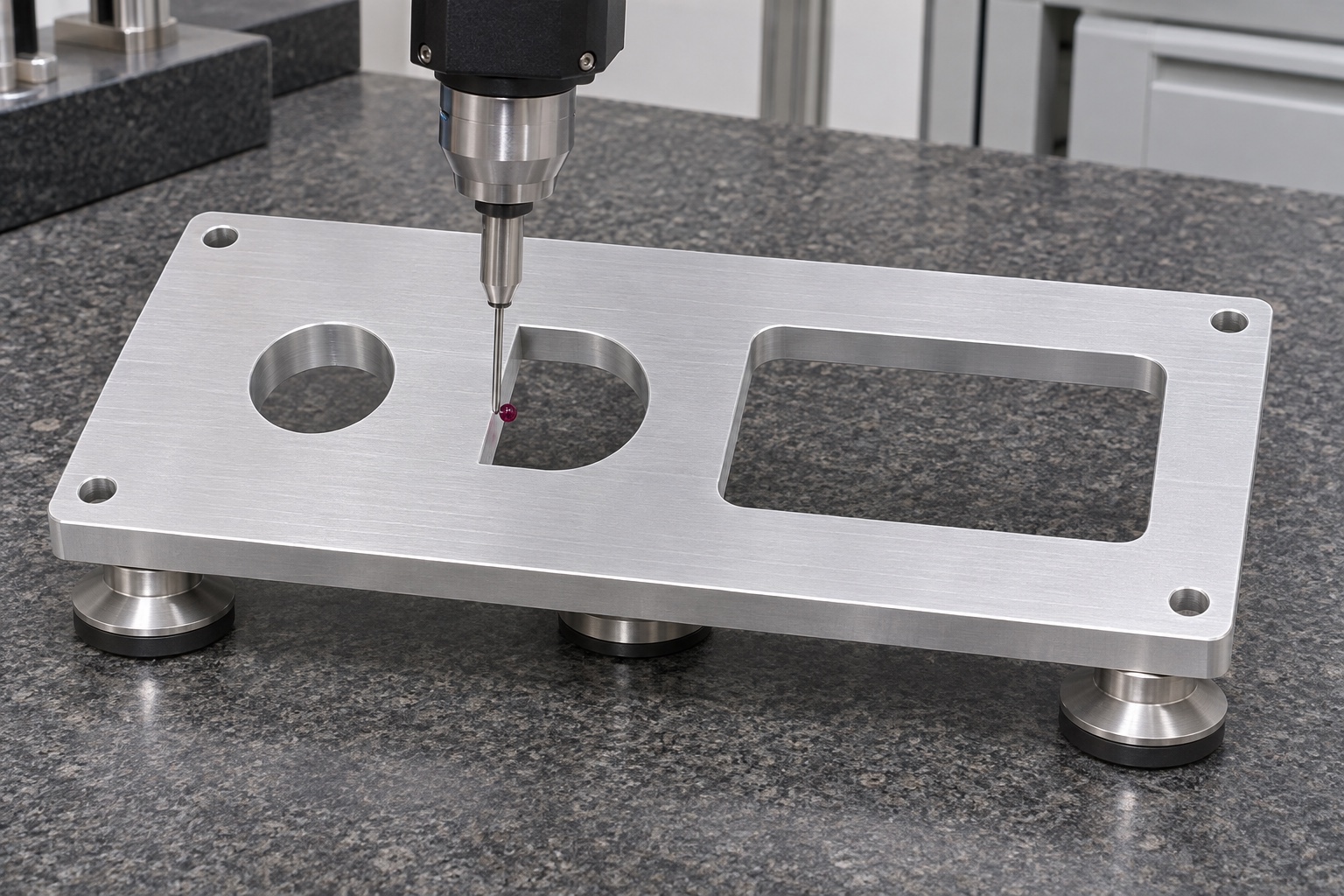
Inspect the pattern and openings independently
The plan should establish the mounting references, then evaluate opening size, location, angular features and relevant face conditions. Suitable coordinate, optical or other dimensional methods depend on access and the actual characteristic. Record the support state and whether measurements apply before or after finishing. A correct diameter does not establish its position in the pattern; a correct pattern does not prove every local keyed profile. The report should identify which regions were measured and which were examined by another approved method. Keep those records separate from a later inert assembly observation so the evidence does not imply that unmeasured geometry was accepted automatically.
Use inert connector envelopes for a defined bench check
A controlled fixture can compare the panel with identified inert references to observe flange seating, key orientation and rear clearance. Record the references, support and positions examined. No electrical connection or operational audiometer is required for this mechanical comparison. A stable mock assembly does not establish hearing-test accuracy, signal performance, grounding or enclosure approval. Those subjects need separate evaluation of the actual system. If a reference conflicts with the panel, stop and identify the contact instead of forcing it through. The useful result is a limited geometric observation under stated conditions, interpreted alongside the dimensional checks and approved interface requirements.
Diagnose interference before enlarging openings
When a reference does not seat, inspect orientation, local edges, thickness, keyed geometry and the rear envelope. Confirm the identity and condition of the reference part. Enlarging the whole opening can remove the symptom while losing a required locating flat or seating relationship. Any correction needs an approved disposition and repeat checks of affected characteristics. Record changes to the fixture or mating references as well. A second fit observation is not equivalent if the setup silently changed. Distinguish a local burr, an incorrect cutout and an assembly-envelope conflict rather than treating all three as a machining problem with the same remedy.
Protect the finished panel and write a clear request
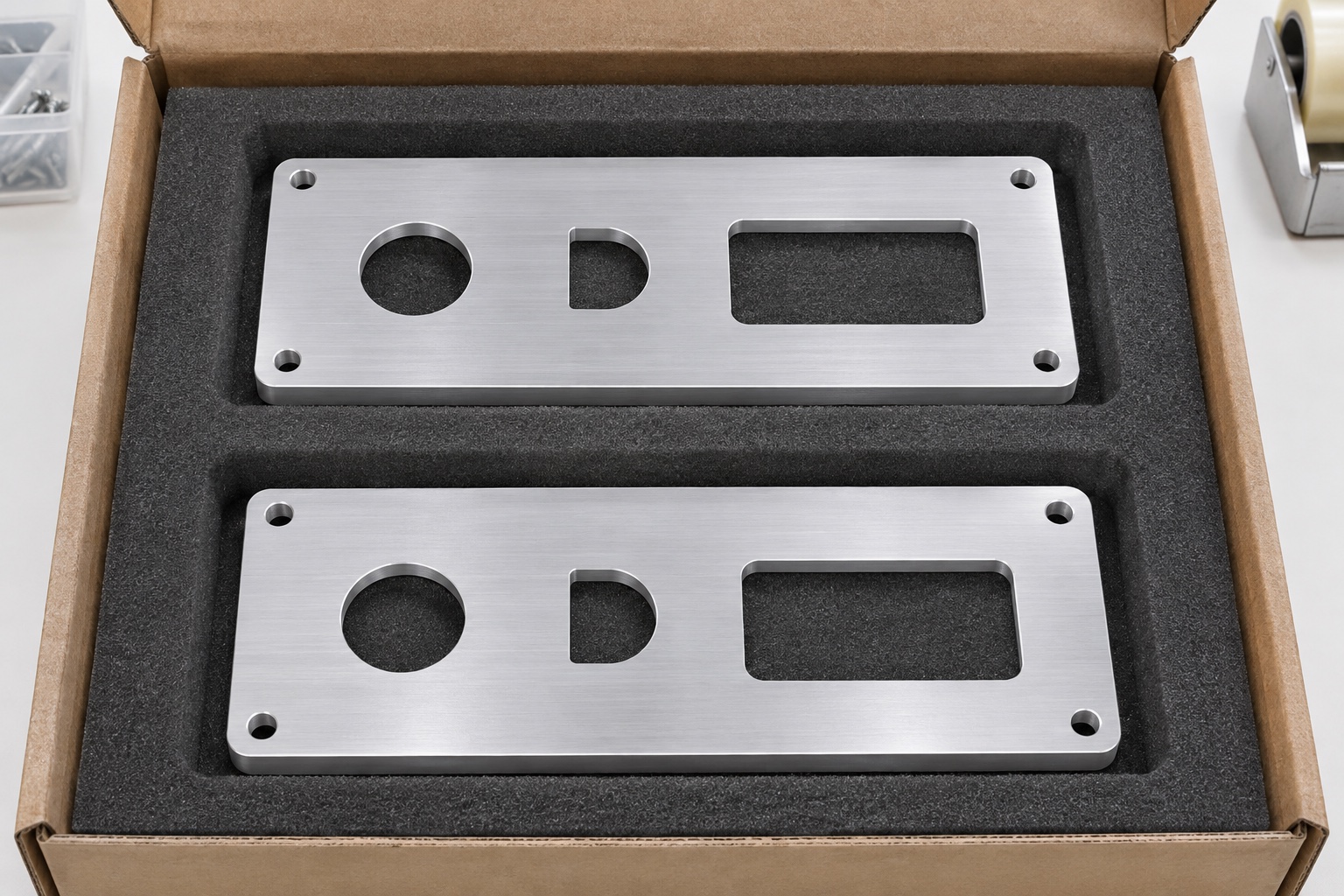
Package panels separately so cutout edges and mounting faces do not contact other metal parts. Support the geometry without bending thin regions, and use only permitted contact materials. Ordinary protection does not establish sterile delivery. A useful request includes the controlled drawing and model, material condition, quantity, final finish, opening details, datum scheme and inspection deliverables. Supply the approved rear envelopes where their comparison belongs in scope. Agree how first-article findings and revisions will be reviewed before a batch proceeds. This creates a verifiable manufacturing task without inventing electrical performance, acoustic calibration or approval of the complete diagnostic instrument.
FAQ
Does a connector entering the hole prove the panel is correct?
No. Size, position, orientation, edge condition and rear clearance are distinct requirements. A local insertion observation cannot establish them all independently.
Why must front and rear views be explicit?
A keyed opening or asymmetric pattern can be mirrored or misoriented while appearing plausible. The drawing must define the intended mounting and viewing direction.
Can rectangular internal corners be assumed sharp?
No. Review permitted cutter radii, reliefs or another approved route against the actual mating envelope before manufacturing.
Does panel finish establish electrical bonding?
No. Appearance or material choice does not provide that evidence. Any electrical requirement belongs in the approved system design and verification plan.
Can an inert reference qualify the audiometer?
No. It observes selected mechanical relationships only. Acoustic calibration, signal quality and instrument safety need separate controlled evaluation.
What should be investigated before widening a cutout?
Check reference identity, orientation, edges, useful wall thickness, keyed geometry and rear interference, then obtain approval and repeat affected checks after any correction.

tanghangyun@oemach.com