
Representative manufacturing scope
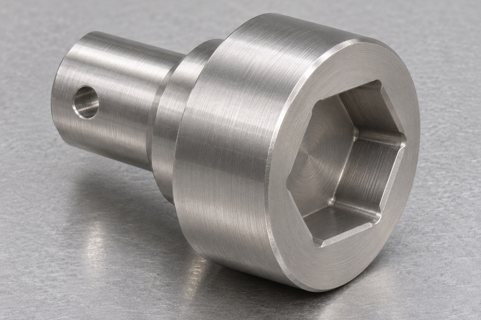
This 316L cryovial capping spindle adapter is a representative CNC machining example, not an actual customer delivery or an approved replacement for a named machine. It considers a stepped stainless body with a locating shank, shoulder, polygon socket and transverse hole. The case explains a proposed route and evidence plan that a real drawing would need to resolve. No customer, certification, achieved tolerance or measured capping result is claimed. The adapter is not used with specimens or an operating capping unit. Geometric component acceptance remains separate from closure torque, vial compatibility, sample integrity and any qualification for low-temperature exposure.

Generic features under review
The body has a narrower rear shank and a broader socket region. The shoulder sets a potential axial reference, while a separately defined feature establishes angular orientation. A polygon pocket and radial cross-hole introduce different machining and inspection requirements. Images show the type of geometry under discussion, not an authoritative interface or production dimensions. The real design must specify what each surface contacts and whether the cross-hole intersects another cavity. A polygon that looks appropriate in a photograph is not evidence that it mates with a commercial cap or drive. Its actual construction must follow the owner's controlled model and drawing.
Inputs required before quotation
The package would identify the 316L material, stock form, quantity, locating references, socket profile, corner condition, useful depth and transverse-hole requirements. It would define final finish, cleaning and inspection deliverables where applicable. A drawing should distinguish a locating fit from a clearance feature and should not leave orientation to interpretation. Unresolved mating or exposure requirements return to the responsible designer before release. The supplier should not choose them from a generic application label. This example supplies no device-specific dimensions. A real quotation would need to state any access limitation or assumption clearly rather than letting an attractive image stand in for an approved specification.
Stock preparation and identity
The proposed route begins with identified 316L stock matching the actual order. Allowance should support the turned references and provide a practical grip during later operations. Material and revision identity remain associated with the blank through machining and finishing. A proposed substitution needs review even if the alternative appears visually equivalent. Where a later treatment affects dimensions, the process plan identifies the relevant intermediate and final inspection conditions. This case does not claim that material certification or a treatment was delivered. It describes the records a real manufacturing order would need to connect stock, operations, observations and the accepted component.
Proposed turning sequence
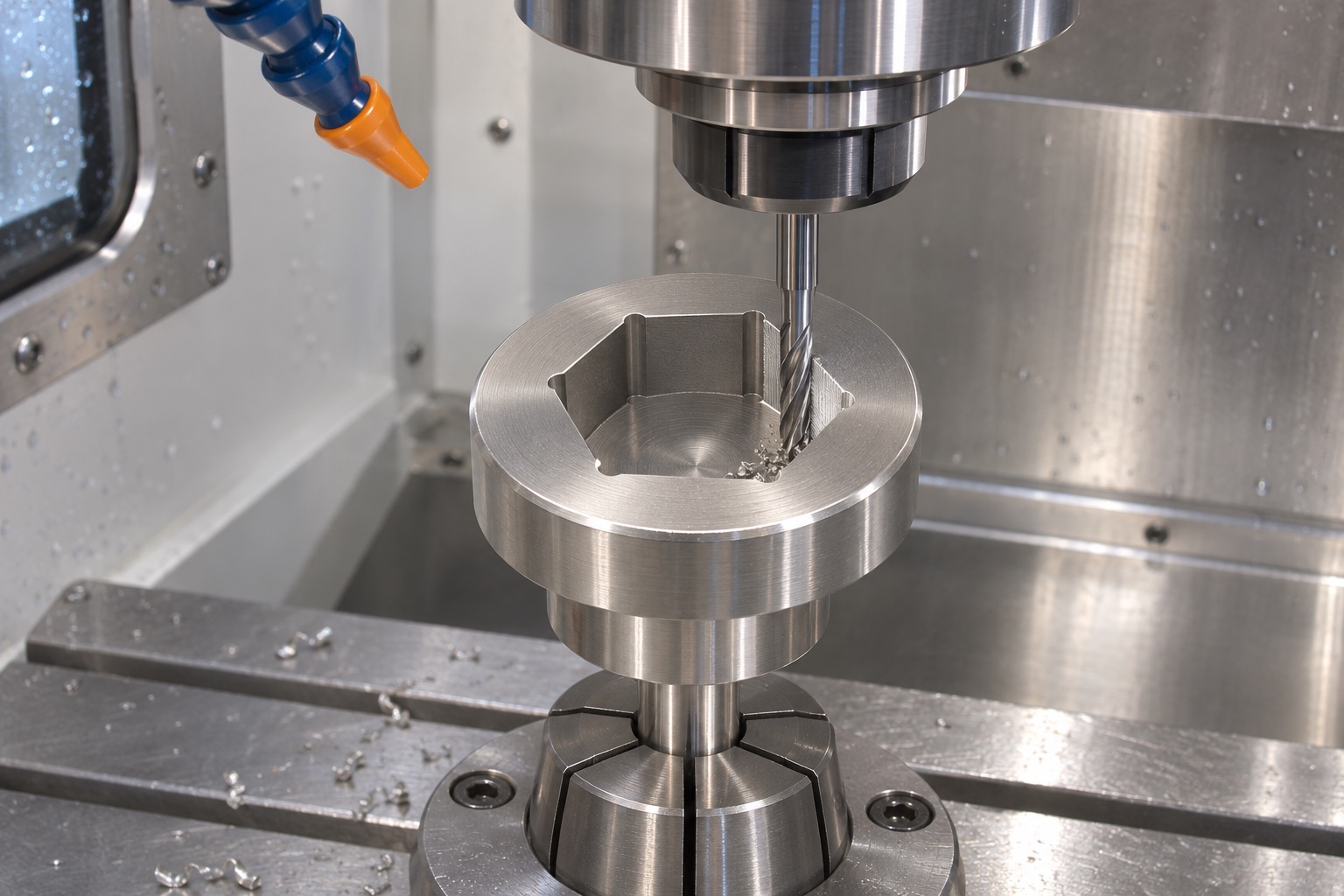
A turning stage would establish the locating shank, axial shoulder and accessible exterior regions while retaining a stable support condition. The setup identifies useful locating lengths separately from entry chamfers and reliefs. The process sheet should show where clamp contact occurs and which surfaces are protected for the next stage. The actual blank, tooling and geometry determine the cutting conditions; no universal parameters are offered here. If another turning setup is required, its reference recovery must be documented. The useful question is whether the route preserves the drawing relationships, not whether the component appears centered while held in a particular chuck.
Socket milling and corner review
The socket operation would recover the shank and shoulder references in a defined fixture. The polygon's functional flats and corner clearance need separate review because a rotating cutter cannot create an ideal sharp internal corner. Approved reliefs or a different route must agree with the model and drawing. Simply increasing every flat to clear an unreviewed mating reference is not a valid substitute. The plan also considers the useful wall depth and the distinction between bottom clearance and an axial stop. No achieved socket fit is claimed; the proposed route must still be qualified against the requirements and actual measurements for a real order.
Transverse feature and edge finishing
The cross-hole is located from the drawing's axial and angular references rather than from a convenient unqualified surface. Tool entry, exit and any internal intersection are reviewed before machining. The drawing defines the permitted edge condition so deburring does not change the functional socket, locating shoulder or hole geometry. After finishing, affected characteristics are inspected again. A passing pin cannot accept an inaccessible intersection automatically. If the geometry prevents the proposed examination, resolve that issue with engineering before production. The example treats this as a planning requirement, not as evidence that an actual component was manufactured without burrs or passed a dimensional report.
Proposed first-article measurements
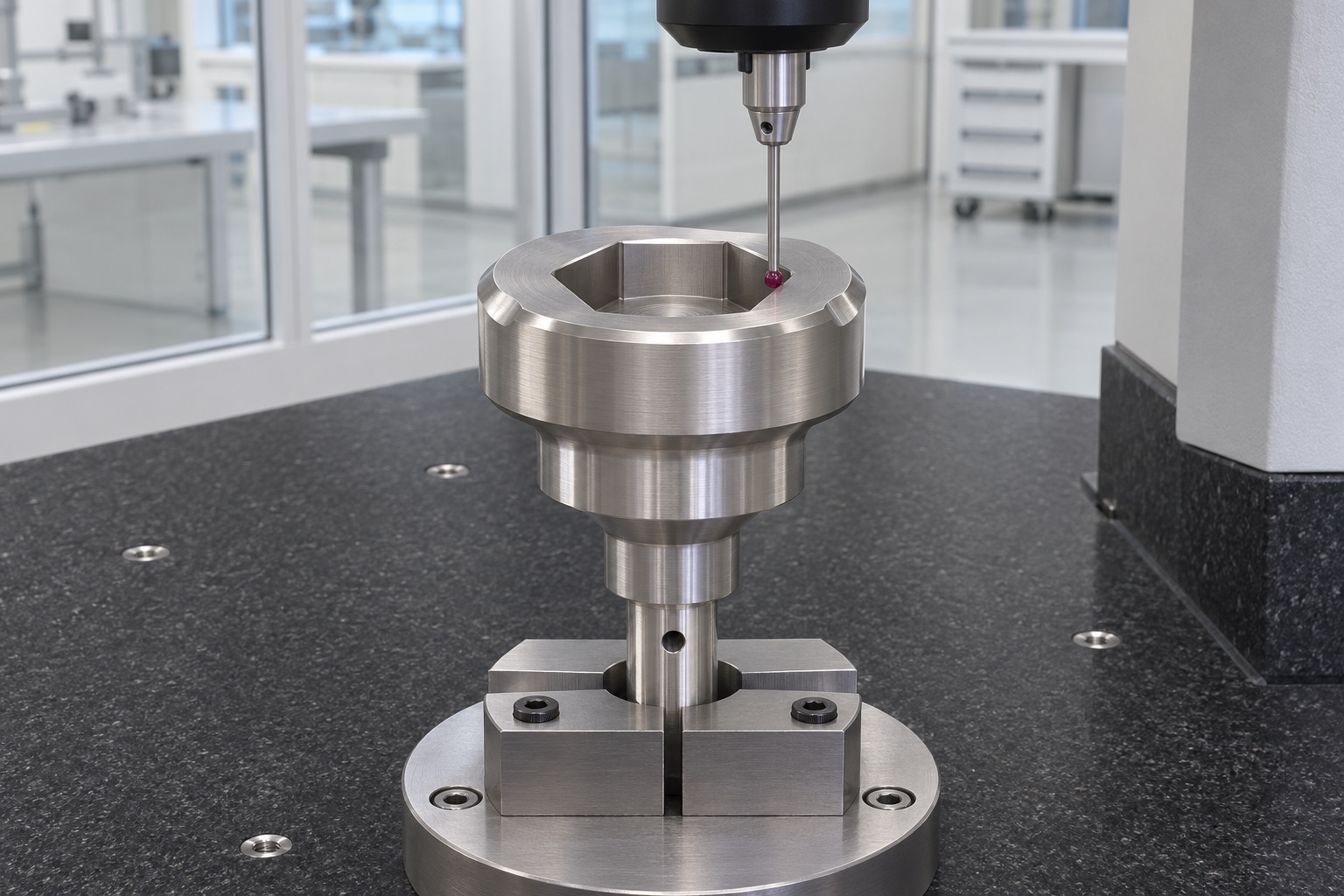
A real inspection list would identify the shank size and axis, shoulder position, socket dimensions at defined depths, corner condition and the cross-hole's location. It would record the datum structure, support and method used for each characteristic. Coordinate, optical or other appropriate methods depend on actual access and required uncertainty. The report distinguishes measured relationships from a local insertion observation. No measured results appear in this representative case. The proposed evidence structure would need actual traceable observations for part identity, drawing revision, material requirement and the final process condition before it could support acceptance of an ordered component.
Inert reference comparison
After dimensional checks, a separate engineering fixture could compare the adapter with identified inert references. The procedure would define support, orientation and the contact observations being recorded. No vial, sample or powered capping mechanism is used. A reference that enters the socket can help identify local interference, but the observation does not prove cap torque, closure integrity or low-temperature suitability. These require their own approved evaluations. Keeping the comparison separate from the dimensional report makes its limited purpose clear and avoids presenting a dry fit as an endorsement of a complete specimen-handling process or a commercial machine interface.
A possible obstruction and review path
Suppose an inert polygon reference stops before the intended depth. The next step would compare the entry, corner clearance, bottom geometry, reference identity and alignment against the measured component. It would not be to enlarge the pocket immediately. This scenario illustrates a review process rather than an observed production defect or a successful repair. An approved correction would identify affected features and require repeat measurement, followed by the same controlled reference comparison. If the design changes, a new revision separates those parts from components evaluated against the earlier requirement. Changing the reference or fixture must also be recorded so the second observation remains interpretable.
Packing and record continuity
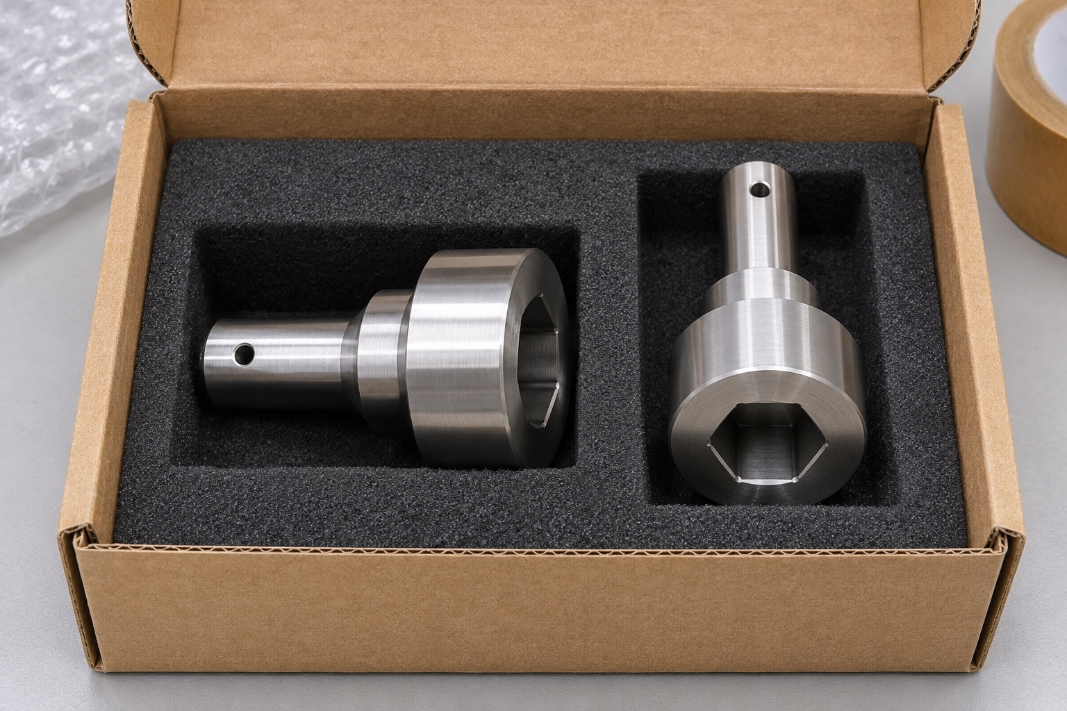
The proposed packaging separates adapters and supports robust exterior areas without damaging the shank, shoulder or socket mouth. It avoids unapproved closures or inserts that leave residue in the interface. Material, part and revision identity remain linked with the corresponding inspection records. Ordinary protective packing is not a sterile barrier, a cleanliness qualification or proof of exposure compatibility. Such requirements need their own agreed processes and evidence. A receiving team should be able to identify the accepted revision and repeat the dimensional checks without first encountering transport damage or a mixture of similar-looking adapters associated with different interface requirements.
Developing the example into an order
Provide the final controlled model and drawing, material specification, quantity, final finish and inspection deliverables. Highlight locating length, shoulder reference, socket flats, corner clearance, depth and cross-hole relationships. State whether any separate coupling or hardware belongs in the scope. Discuss difficult tool or measuring access before committing to a critical requirement. Agree how first-article findings and proposed changes will be reviewed before a batch proceeds. The example offers a manufacturing discussion and evidence structure; it does not replace a released interface, actual measurement results or approval of an automated laboratory capping process for a defined vial and specimen-handling application.
FAQ
Is this an actual cryovial equipment delivery?
No. It is a representative machining example without customer delivery data, achieved tolerance claims or measured capping results.
Can the picture define the socket interface?
No. A controlled model and drawing must define useful flats, corners, depth and references. The image does not establish commercial compatibility.
Is low-temperature suitability demonstrated?
No. Application naming does not qualify a material or component for an exposure condition. Separate requirements and evidence are needed.
What would be checked on a first article?
The actual drawing controls the list. This example discusses shank, shoulder, socket dimensions and the transverse feature's position and condition.
Why separate an insertion trial from inspection?
It observes one reference combination and setup. It does not independently establish every size, geometric relationship or surface requirement.
Does the case authorize installation or specimen use?
No. It does not establish machine compatibility, closure performance or approval for specimen handling and is not an installation instruction.

tanghangyun@oemach.com