
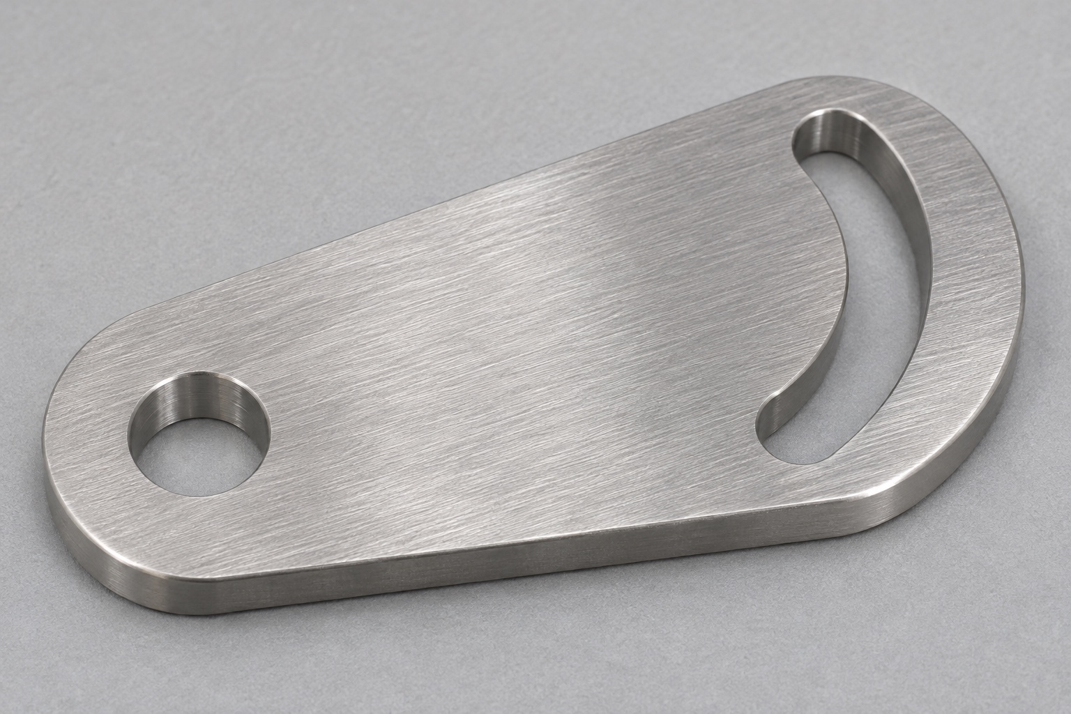
Representative case and scope
This 316L centrifuge lid-latch cam plate is a representative CNC milling example, not a completed customer delivery or a released replacement part. It considers a flat stainless plate with a pivot bore and a curved through-slot. The purpose is to explain the proposed manufacturing and inspection questions that a real drawing would need to resolve. No customer, certification, measured production result or safety performance is claimed. The component is not installed in an operating centrifuge. Its dimensional review is separate from latch retention, interlock operation and equipment approval, which cannot be established by a component image or an unloaded movement observation.

Geometry selected for manufacturing review
The generic plate has a rounded exterior, a plain pivot bore toward one end and a curved closed slot toward the other. A principal face supplies an axial reference, while a separately defined feature controls orientation. The slot creates a follower path whose relationship to the pivot matters more than its appearance within the outer silhouette. The drawing must identify its actual profile, useful wall height and end conditions. Images show the type of geometry under discussion, not controlled dimensions or an authorized part for a named instrument. Any real order would replace the generic layout with the owner's approved model and drawing.
Required inputs before quotation
The design package would specify material, thickness, critical features, geometric references, edge conditions and the required final surface state. It would identify whether the bore is a locating interface or a clearance feature. The slot's profile requirement should agree with the model instead of being described only by an incomplete radius note. Quantity, inspection deliverables and packaging constraints also belong in the quote review. Where a feature cannot be inspected by the proposed method, resolve the issue before accepting the order. The machining supplier should not invent missing latch or device requirements to make the package appear complete.
Identified stock and preparation
The proposed route starts with stock matching the approved 316L specification and any documentation requirement. The blank provides sufficient allowance for the locating face and the exterior without forcing unsupported cutting near a thin web. Identification follows the material through preparation and subsequent operations. A suggested material or stock-form change would need review before use. If later surface treatment is required, define the relevant intermediate and final inspection states. This example does not claim a treatment or material certificate was delivered. It describes the information that an actual manufacturing record would need to connect to the finished component.
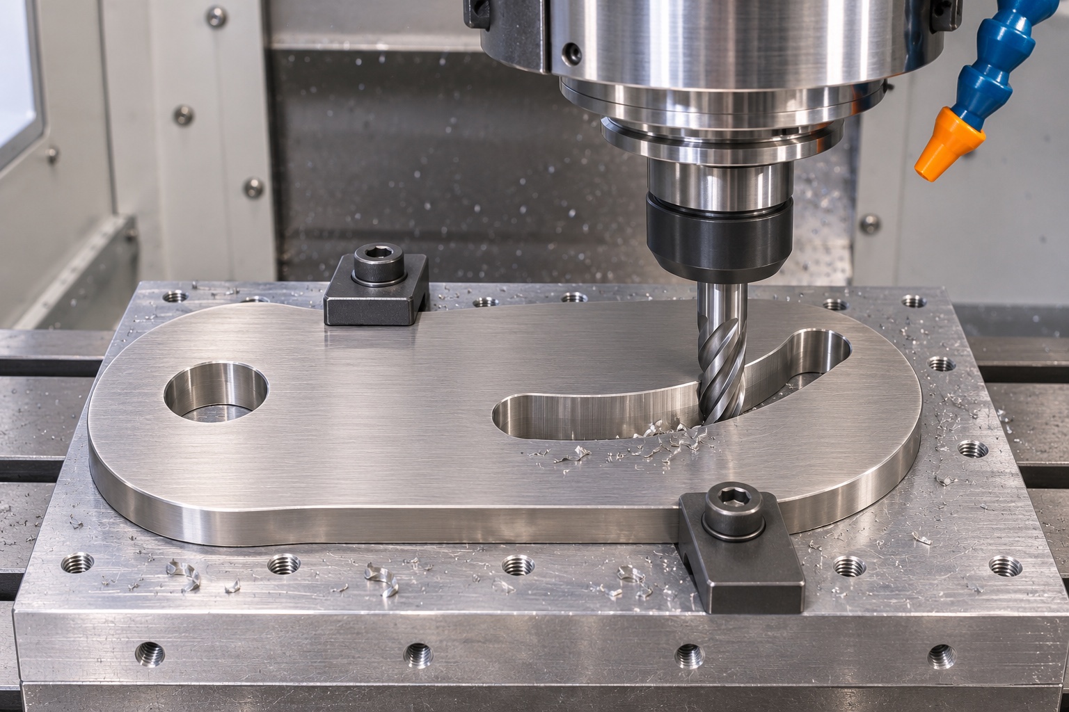
Establishing a repeatable support condition
A fixture would support robust regions of the plate while keeping both sides of the slot accessible as needed. The setup review identifies clamp contacts and the direction in which they load the part. It should consider the reduced stiffness after roughing, not just the behavior of the original blank. If the part must be reversed, the procedure must recover the specified datum structure. Merely pressing the plate flat against a fixture does not establish its free-state condition. The proposed plan therefore separates the support used for cutting from the support state required when the component is accepted by inspection.
Proposed milling sequence
The proposed sequence prepares the reference face, roughs the accessible features and preserves allowance for finishing the pivot and slot relationship. It reviews cutter access through the curved path, particularly near the closed ends where engagement can change. If finishing both related features in a common setup is practical, the route would describe that reference continuity. If not, it would identify the transfer method and checks. No universal cutting parameters or achieved tolerance are asserted. The relevant question is whether the selected route can produce the actual drawing requirements with a reproducible setup and an inspection method capable of evaluating the result.
Edge finishing without changing the path
The through-slot requires attention at both entrance and exit edges. A proposed finishing step would remove prohibited raised material while preserving the functional profile and useful wall height. The drawing should define where an edge break is allowed and where it must remain limited. A hand-polished entrance cannot stand in for inspection of the full wall. After any finishing operation that can alter geometry, the affected characteristics would be checked again. If access is inadequate, the issue belongs in engineering review rather than an unsupported statement that every internal edge is acceptable. A real process would document the method and resulting evidence.
Proposed first-article report
The first-article plan would identify the principal face, pivot bore, angular reference, plate thickness and the required slot profile. It would state the method, measured regions and support condition. Where coordinate or optical inspection is proposed, the actual access and characteristic determine its suitability. The report should distinguish local width checks from evaluation of the path relative to the pivot. No measured results are supplied in this representative case. The plan is an evidence structure that a real order would need to populate with traceable observations associated with part identity, drawing revision and the final process state.
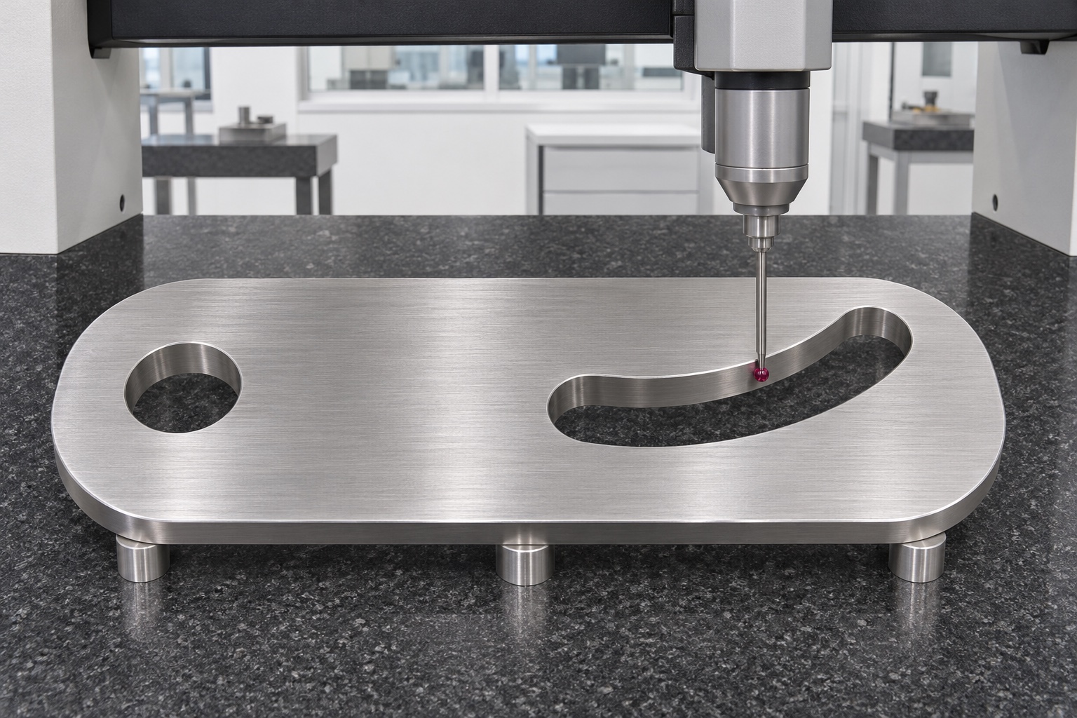
Unloaded geometric comparison
After dimensional checks, a separate inert fixture could use identified pivot and follower references to observe contact along a defined portion of the curve. The procedure would record orientation, support and the positions inspected. It would not use a working centrifuge, apply a retention load or bypass a safety device. Such a comparison may help locate interference in the specified bench arrangement, but it does not establish latch security or control-system behavior. The example keeps that boundary explicit so a local movement observation is not confused with a validated equipment function or permission to install a component.
A possible discrepancy and review path
Suppose a reference follower moves freely near one end but contacts the wall at an intermediate position. The next step would be to preserve the observation and compare the relevant measured profile, fixture references and edge condition. It would not be to enlarge the entire slot automatically. This scenario illustrates a decision process, not a report of an actual production defect or a successful repair. A proposed correction would need an approved disposition and repeat inspection of affected characteristics. If the design itself must change, a new controlled revision should distinguish that part from components evaluated against the earlier geometry.
Packaging and record continuity
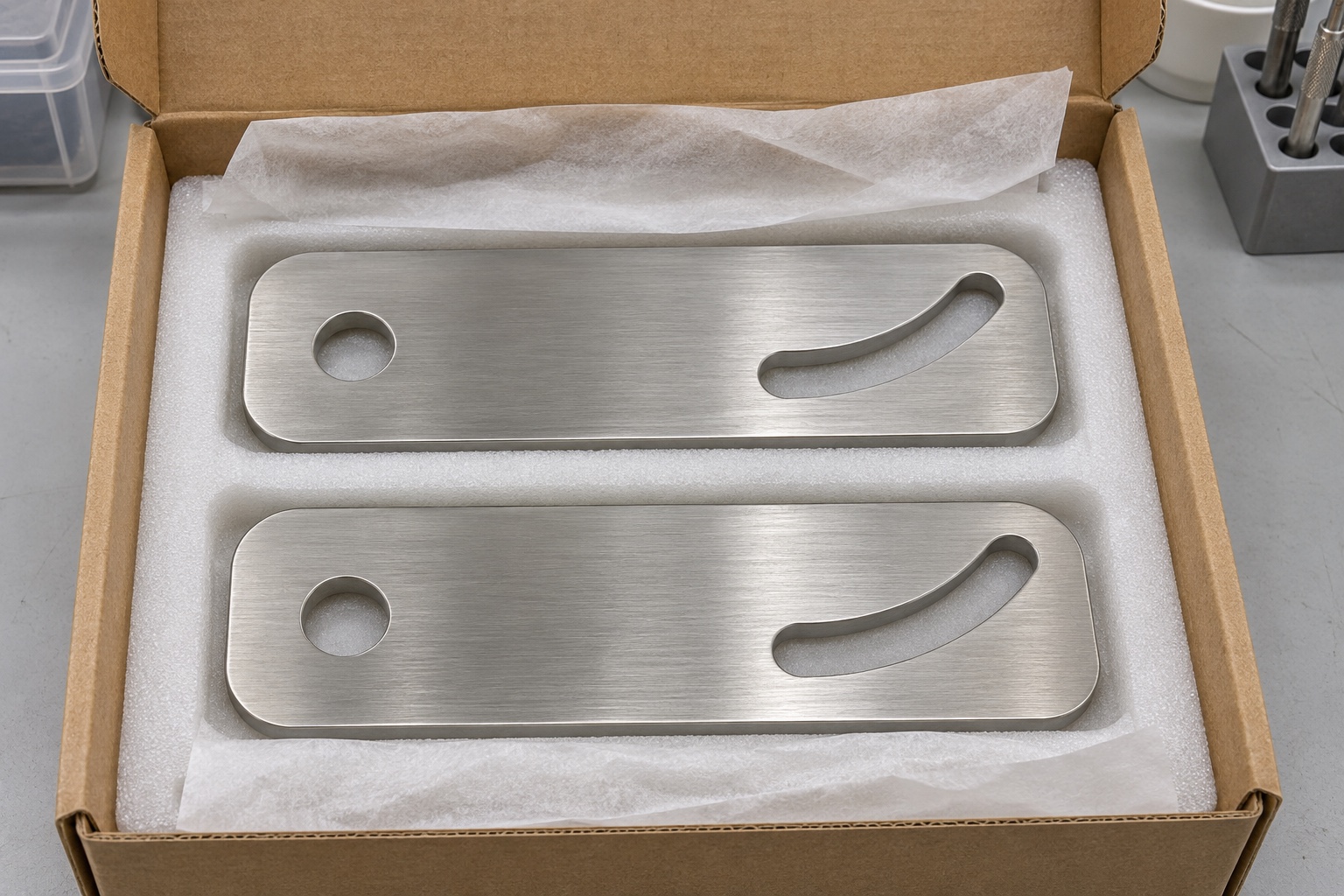
The packaging proposal keeps plates separated and supports them without bending the main face or loading a narrow web beside the slot. Contact materials must comply with the actual handling requirements. Identification should remain associated with the material and inspection records without adding an uncontrolled mark to a functional surface. Protective packing preserves geometry in ordinary transport; it is not a sterile barrier or a medical qualification. If a defined cleanliness requirement applies, it needs separate instructions and acceptance evidence. The receiving team should be able to repeat the dimensional checks without first finding damage caused by packaging or mixed revisions.
Turning the example into an order
A real request would add the final model and drawing, stock requirement, quantity, finish condition and the agreed inspection deliverables. Highlight the pivot-to-slot relationship and identify the actual orientation reference. Resolve any disagreement between a local width dimension and the intended profile before production. Agree how first-article findings and rework proposals will be reviewed before releasing a larger batch. The value of the example is a clear proposed route and evidence plan, not a promise of equipment performance. Component acceptance must follow the actual released requirements, while the complete latch and centrifuge remain subject to their separate approval process.
FAQ
Is this a completed centrifuge customer case?
No. It is a representative machining example with a proposed route and inspection plan, without customer delivery data or measured performance results.
Can the image define the follower path?
No. The approved drawing and model must define the slot boundaries, references and acceptance requirements. A photograph is not a production specification.
Which geometry would a first article check?
The actual drawing determines the list. This example discusses the principal face, pivot bore, orientation reference, thickness and curved-slot profile.
Does the case claim an achieved profile tolerance?
No. No dimensional capability or measurement result is asserted. The real order must define requirements and provide actual acceptance evidence.
Why keep a follower comparison separate from inspection?
A fit observation addresses a particular setup and reference combination. It does not independently prove all dimensional or geometric characteristics of the plate.
Does this example authorize latch installation?
No. It does not establish device compatibility, retention, interlock behavior or operational safety, and is not an installation instruction.

tanghangyun@oemach.com