
Scope of this representative machining case
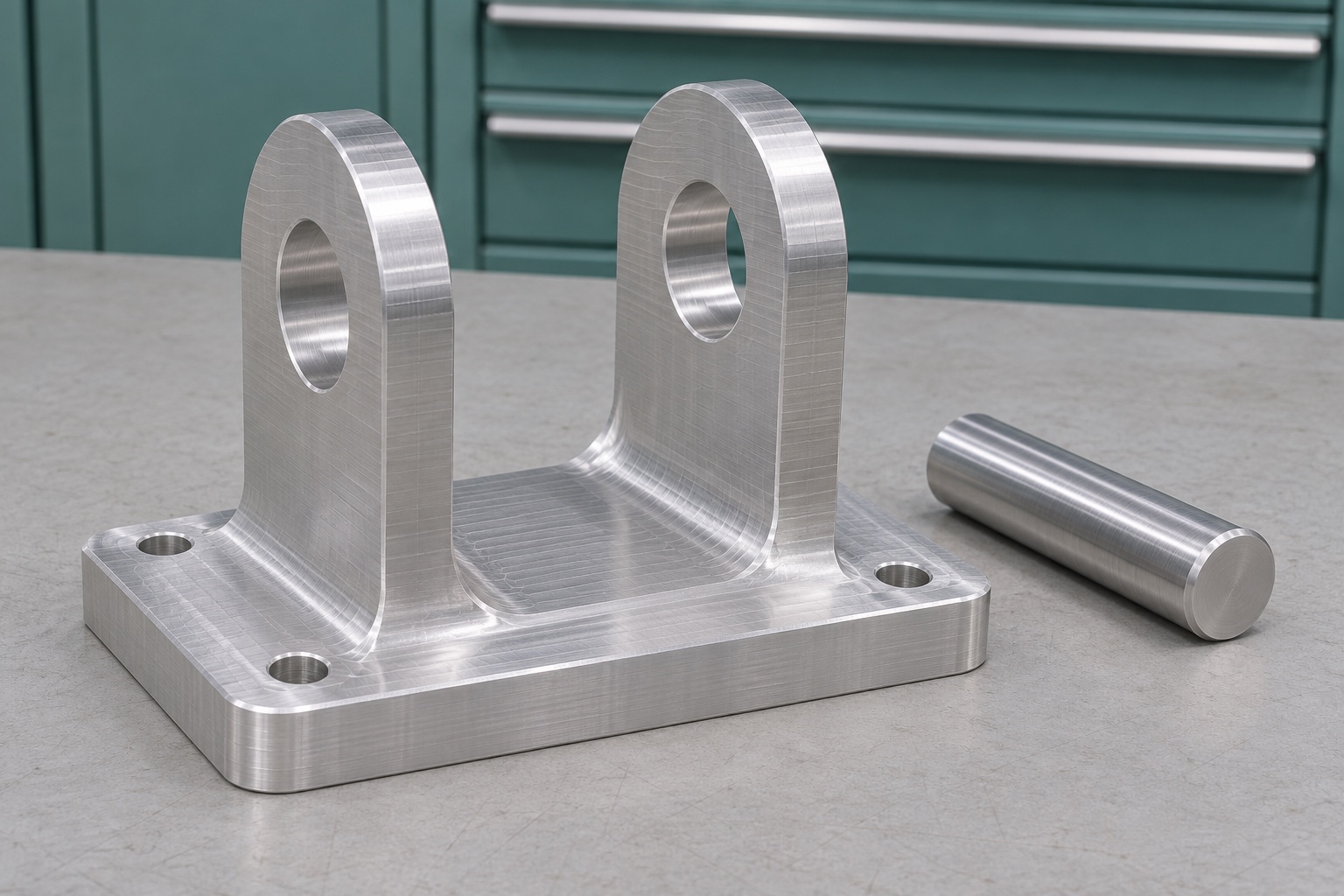
This medical cart monitor tilt bracket is a representative CNC milling example, not a completed customer delivery or an approved replacement part. The case follows a proposed route for an aluminum fork with a mounting region, two pivot ears and opposing shoulder faces. It describes the manufacturing inputs and evidence that would need to be agreed for a real order. No load capacity, certification, clinical compatibility or measured production result is claimed. The geometric example is separate from a complete monitor support system, whose structural, retention and stability requirements cannot be established by a component image or a dry fit.

Geometry chosen for the process review
The generic bracket has a flat mounting base and two upright ears carrying a shared pivot pin. The gap between them accommodates a separately defined mating piece. A controlled drawing would specify the mounting pattern, ear spacing, bore sizes, radii and required geometric relationships. The images do not prescribe a bolt pattern for a named cart or monitor. The useful manufacturing question is how to preserve the pivot relationship to the mounting plane while producing accessible shoulder faces. This makes the example more specific than a general aluminum milling discussion without turning it into an installation instruction.
Required drawing and quotation inputs
The starting package would identify the 6061 alloy condition, stock form, quantity, finish state and datum scheme. It would also define which bores and faces are functional and what inspection evidence is required. If bushings or other mating components are involved, their interfaces must be resolved in the design rather than improvised during assembly. Unanswered questions about a deep pocket, thin ear or inaccessible measurement should be raised before the quote is accepted. The example is not a substitute for those decisions. A real production release would need the owner's approved revision and a clear acceptance plan.
Stock preparation and identity
The proposed process begins with traceable stock matching the actual material specification. A blank is selected with sufficient allowance for locating surfaces and the fork pocket. Its condition should be recorded before machining so later changes do not become unexplained assumptions. The plan does not substitute a different alloy or temper to simplify procurement. If a specified surface treatment follows machining, the route identifies the relevant intermediate and final inspection states. This case does not assert that a coating, heat treatment or material certification was delivered; it describes the information that a real manufacturing record would have to establish.
Establishing the mounting reference
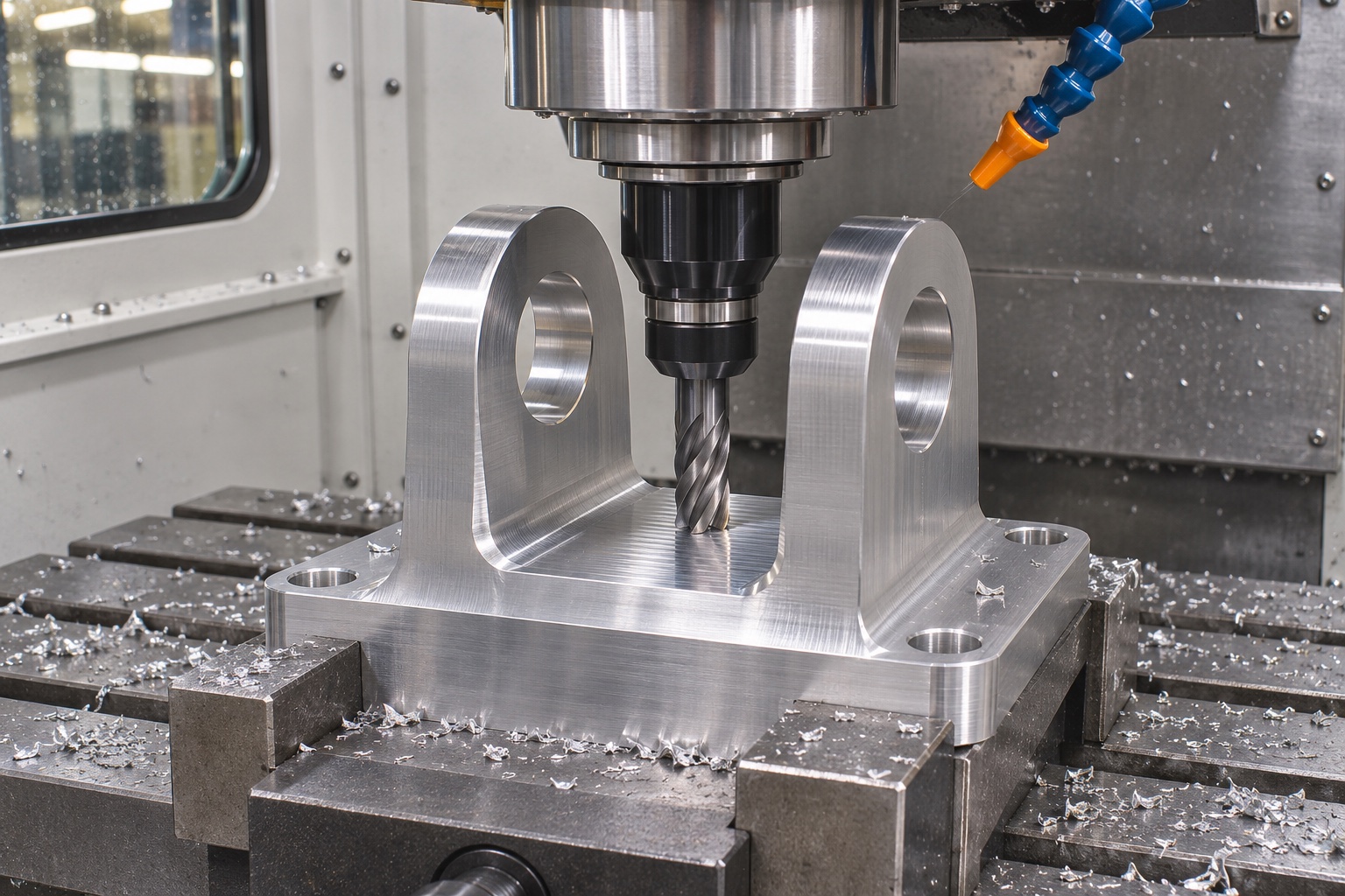
A first setup would create or qualify the mounting face and reference features used by the later operations. The plan should show how the part rests and where clamp force is applied. That prevents an operator from locating on a convenient but nonfunctional surface when reversing the part. Inspection of the reference condition should occur before it is used to establish the pivot features. The exact sequence depends on the released geometry and available equipment. The central principle is that the mounting datum follows the component through the route rather than being recreated differently by each operation and each inspector.
Milling the fork and inner faces
The pocket between the ears would be roughed with support retained, then finished using tools compatible with the gap and corner geometry. Review whether the cutter can reach the inner shoulder regions without excessive projection. Clamp contact must not squeeze the ears into a shape that disappears when the part is released. The drawing should identify the actual face-spacing requirement and any permitted radii. This example does not prescribe a universal cutter diameter or corner radius. Those choices must follow the design and process review, with any proposed geometry change approved before it becomes part of the manufacturing route.
Producing the paired pivot bores
The proposed route treats both pivot bores as a related feature set rather than independent holes. Where practical, the finishing sequence would preserve a common reference through the two ears. Tool reach, chip clearance and access to the second bore require review. If a transfer is unavoidable, the setup must recover the approved datum structure. A reference pin may support a later fit observation but cannot replace dimensional evidence for the axis relationship. No coaxiality value or batch capability is claimed here. The real drawing and inspection method determine what would be measured and what evidence would support acceptance.
Proposed first-article inspection
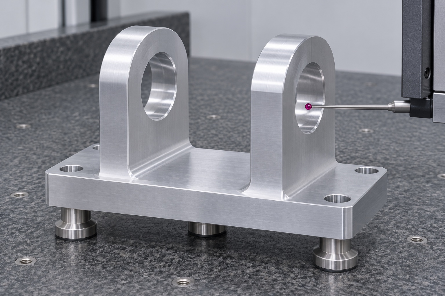
The inspection list would include the mounting plane, fastening pattern, individual pivot sizes, their required relationship and the opposing shoulder spacing. It would identify measurement locations that exclude chamfers and reliefs unless those are the characteristic under inspection. A coordinate or other suitable method would be selected according to access and the actual tolerances. Support and part condition must be recorded, particularly if the ears can deflect. This is a proposed list, not a supplied report of measured results. A useful real record would connect each observation to a characteristic, part identity and drawing revision.
Unloaded bench assembly check
After dimensional acceptance, an identified dummy plate and reference pin could be used in a separate inert fixture to examine movement clearance. The procedure would define the movement range and record contacts at intermediate positions as well as endpoints. It would not use a live monitor or an operating medical cart. The resulting observation could identify geometric interference under that setup, but it could not establish safe support of a device, holding torque, fatigue life or stability. Keeping the bench check separate from the dimensional report prevents a local fit observation from becoming an unsupported claim about the entire support system.
Example decision when movement is restricted
If the unloaded fixture showed restricted motion, the next review would check the reference pin, local edges, bore relationships, shoulder spacing and support condition. The team would preserve the observation before choosing an action. Reaming both holes until motion becomes free is not an automatic solution, because it may change the intended fit without addressing the cause. This scenario illustrates a review process rather than an actual production failure. Any permitted rework would need a documented disposition and repeat inspection of affected features, followed by the same controlled fixture check using identified references.
Finish protection and packaging proposal
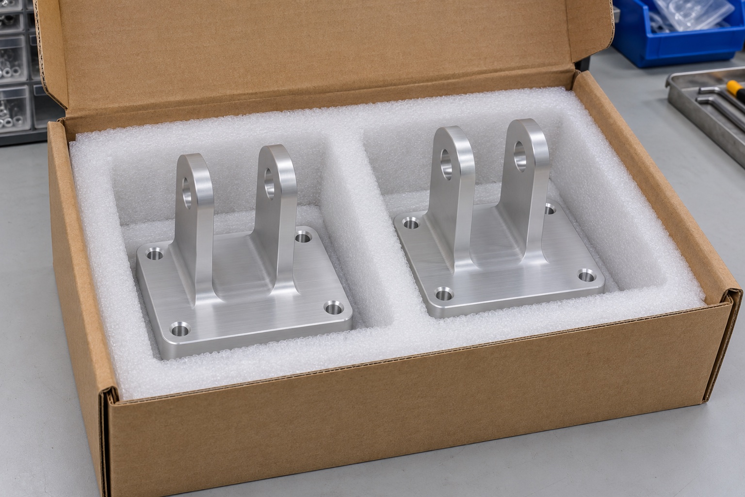
The packaging proposal keeps the inner shoulders and bores away from adjacent metal parts, while supporting the bracket at robust exterior regions. It avoids packing forces that close the gap between the ears. Any wrapping, labels or marking should follow the approved handling requirements and preserve identity through delivery. Ordinary protective packing is not a sterile barrier or a medical qualification. If a surface treatment is specified, its acceptance records must remain associated with the component, but a visually uniform finish cannot substitute for them. The receiving team should be able to inspect the part without finding that its functional surfaces were damaged in transit.
What a real order would add
To turn this example into a manufacturing request, provide the final model and drawing, material condition, quantity, treatment requirements and inspection deliverables. Highlight the mounting datum, paired pivot relationship and shoulder spacing rather than simply asking for high precision everywhere. Agree how first-article approval and revisions will be handled before a larger batch proceeds. The owner must separately establish requirements for the assembled support system and authorize its use. The value of this representative case is the proposed route and evidence structure; it does not replace a released design, an actual measurement report or the approval of a medical equipment assembly.
FAQ
Is this a delivered medical cart component?
No. It is a representative CNC milling example. No customer order, measured delivery result or compatibility with a specific cart is claimed.
What is the most important geometric relationship?
The drawing must define the pivot features relative to the mounting reference and to each other. Correct individual bore sizes alone are not sufficient.
Does this case claim a monitor load rating?
No. A load rating requires the complete system design and appropriate evaluation. Neither the machining example nor an unloaded fit check establishes one.
Can the image be used as a production drawing?
No. It does not supply controlled dimensions, tolerances or interface approvals. Manufacture must follow the owner's released drawing and model.
Why might a bracket bind after machining?
Possible causes include edges, bore misalignment, incorrect face spacing, reference-part condition or fixture distortion. Inspect before choosing an approved correction.
What records should a real first article include?
Record part identity, drawing revision, material requirements, critical measured characteristics, support conditions and the final finish state, with separate results for any approved bench check.

tanghangyun@oemach.com