
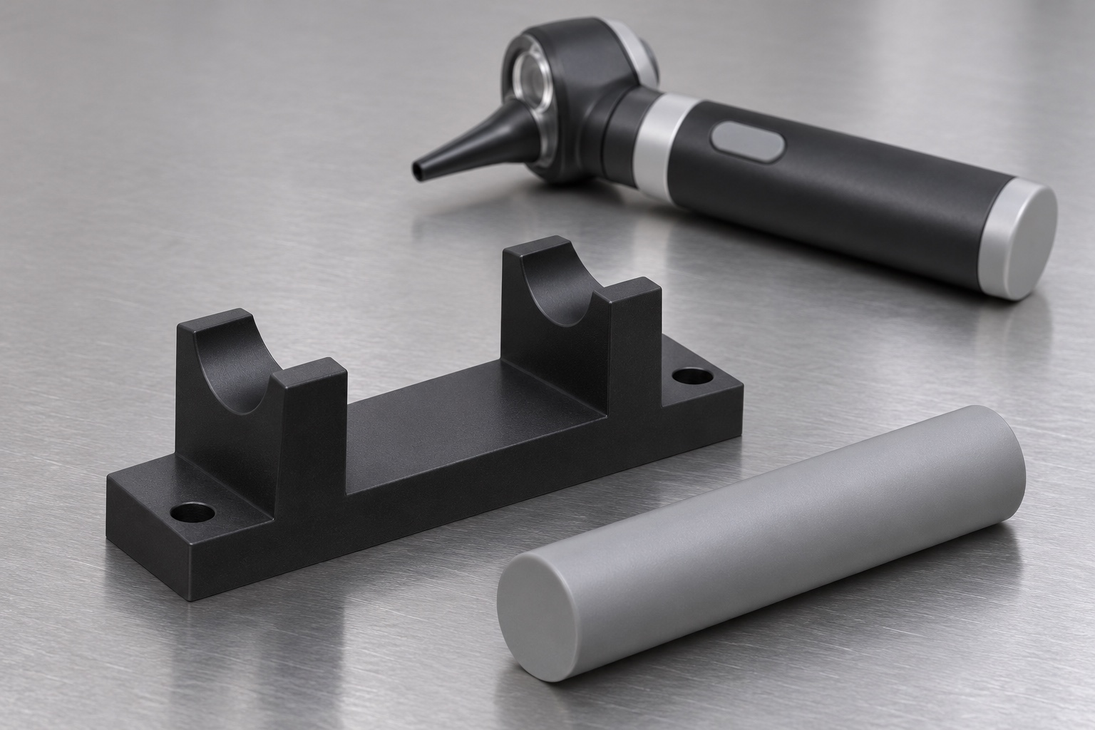
Define the bench purpose
A handheld otoscope can have a power handle and examination head. A passive cradle can support a rigid dummy of the handle for engineering fit checks, but it does not supply power, retain the head during use or approve an accessory. Define whether the task is to compare entry clearance, height, orientation or space around a neighboring panel. Identify the handle geometry from a controlled drawing. The example concerns a non-clinical bench support without batteries or electrical contacts and should not be interpreted as a charger, a patient accessory or a repair procedure.

Put each saddle on an allowed contact region
The two supports should meet the defined exterior regions rather than a label, switch or connector. If the handle changes diameter, draw which saddle corresponds to each region and where each groove ends. A cosmetic shoulder may look stable while touching a feature that was meant to remain clear. Use a side view and cross sections at both stations so a machinist can tell what is intentional. Check how the dummy can be placed and removed without touching a thin rim, and document whether the fixture provides only support or also defines orientation.
Distinguish radial seating from axial location
A shallow cradle can support a round body without preventing it from sliding along its axis. If the fixture needs an axial reference, define a separate stop against an allowed surface and account for the seating sequence. Do not ask a connector to act as a stop unless the controlled setup expressly assigns that role. If rotation must be controlled, state how this is accomplished. The depth of two grooves does not necessarily establish either axis direction or orientation. Each requirement should be tied to a feature and a repeatable way of checking it.
Use one reference frame across both supports
Define the mounting plane and a direction along the block. The two grooves can be related to the same coordinate system even if they are cut in separate operations. Check both individual contour and the relationship between seats. A contour that fits a short plug at each station may still tilt a long dummy. If both grooves are symmetrical, include a way to identify the first and second station in the report. Do not treat mounting-hole clearance as exact positioning unless the drawing provides a separate locating feature.
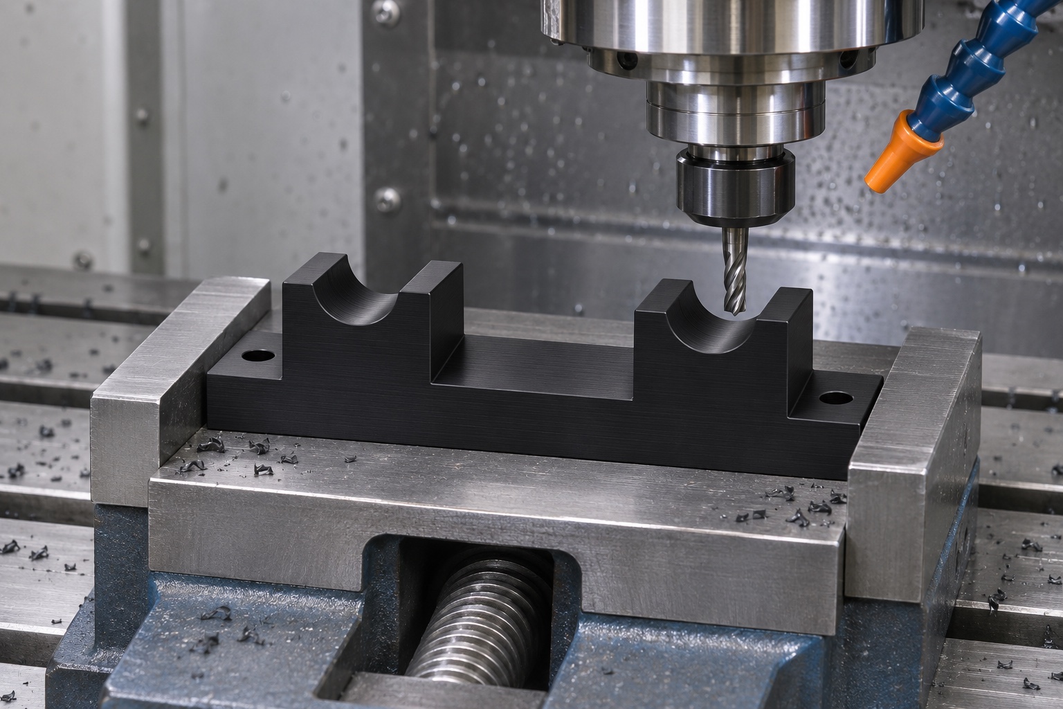
Allow clearance for local handle details
Account for envelope changes around the grip, end cap and any dummy connector feature. A drawing should show how much of the handle remains accessible when seated. If a separate test component must fit near one end, include its swept envelope, not just its nominal outline. The best shape for a support can differ from the best shape for a tight holder; extra side contact may trap the dummy and make an inspection less useful. Agree allowable contact and inspection force before deciding to add a liner or a retention element.
Select stock and finish for inspection repeatability
POM-C can be considered as a machinable polymer for a bench block, but the grade, stock form and final state still need to be specified. Consider whether a support edge could mark a dummy and whether cleaning residue changes the contact. A liner changes the final contour and height, so it should be represented on the drawing and in the inspection condition. Color does not prove grade or suitability for cleaning, electrical insulation or use in a medical device. Leave performance claims to the responsible equipment owner and the approved setup.
Plan roughing and finishing to preserve the references
Establish the base and side references on a supported blank, then rough around both saddle regions while they remain stiff. Allow enough material to finish after checking the released shape. Select a contouring tool and tool path for the actual groove and access. When the two saddles can be finished from a common origin, their relative position is easier to document. If the part must be moved, note how the reference is restored. Avoid squeezing a narrow wall into position and accepting dimensions measured only while the part is clamped.
Check both grooves and their common axis
Record profile data at named usable areas rather than reading an edge break or relief. A measured cylindrical master placed across both saddles can provide a separate observation of seating and axis attitude. Record the master identity and diameter, the support condition and where it was measured. A functional observation does not replace each required contour dimension. Use a known method to distinguish a tilted block from a difference in seat height. The report should give the receiving team enough information to reproduce the setup without using the illustrative picture as a gauge drawing.
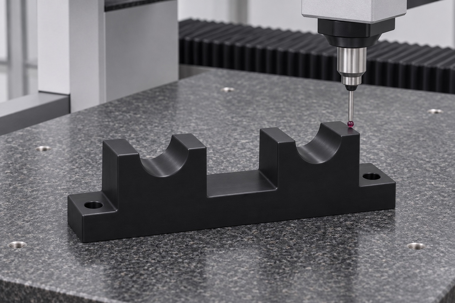
Repeat placement without power or a real instrument
Use an identified inert dummy with no battery, energized contacts or patient-facing instrument. Note the insertion path and where the dummy rests. Remove it fully and repeat the placement if the test is meant to show seating consistency. An observation that follows the dummy after it is rotated may indicate a reference issue rather than a cradle error. Inspect the edges and nearby hardware separately. Even a successful repeat placement establishes only a mechanical relationship in that setup, not retention under load, charging behavior, electrical safety or device compatibility.
Record changes instead of tuning a single sample
Check for debris, a raised edge and mounting distortion before cutting a groove deeper. If a change is approved, preserve the original result and recheck affected features using the same reference where appropriate. A part can look better after polishing while losing the datum the inspection needs. Specify allowed edge breaks and contact finish, and keep identification marks away from functional surfaces. A clean-looking block is not proof of disinfection or sterility. Normal bench cleanup should not be repurposed as a procedure for clinical instruments or their accessories.
Protect the saddles between trials
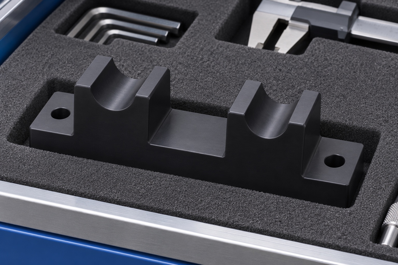
A fitted insert can support exterior faces while keeping the two groove edges free of impact. Do not press a loose dummy handle into the cradle during shipping, since it can mark the supports or move in the package. Label the cradle and dummy separately with their identifiers. At receipt, check whether the insert shifted or was compressed before relying on previous measurements. Any defined cleanliness or storage requirement needs its own evidence. A simple protective package does not demonstrate a sterile barrier or a validated shelf life.
Request evidence for the stated bench task
Send the controlled cradle and dummy drawings, permitted contacts, material grade, support state and inspection stations. Ask for the measured contours, their relation to the base and any separate placement observations. The supplier should list open questions instead of assuming the concept fits a commercial product. A real instrument or charger would need its owner's approved design and verification. The purpose of the documentation is to show which features were compared and under which conditions, so mechanical evidence is not mistaken for electrical, clinical or compatibility evidence.
Manufacturer background reference: www.hillrom.com.
FAQ
Does this cradle charge an otoscope?
No. The bench concept is entirely passive, has no electrical contacts and does not authorize use with an operating device.
Why use two saddles?
They support two defined exterior regions. Their heights and alignment should be checked together as well as at each station.
Does the cradle fix the handle axially?
Not by the grooves alone. A separate approved stop or other feature would be needed if axial location is part of the bench task.
Can a single plug verify the whole setup?
No. A master can help check seating, but the drawing may also require individual profile, position and mounting checks.
What if one end sits higher than expected?
Check the dummy, saddle contours, debris and base support before altering the groove. Record the original setup and observation.
Is the illustrated package for clinical use?
No. It illustrates physical protection for a bench fixture, not a validated sterile or cleanroom condition.

tanghangyun@oemach.com