
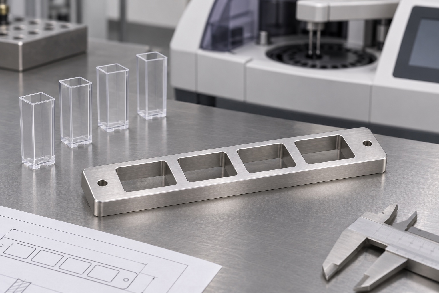
Establish the scope of the example
This representative CNC manufacturing example considers a short 316L stainless rail with four rectangular pockets in one row and a mounting hole at each end. It is intended to demonstrate geometry and an empty-surrogate placement check on a bench. It is not a customer delivery, a replacement analyzer part, a clinical sample holder or a validated assay tool. The illustrations show a generic configuration, not a released drawing or a measurement. A real order would define the pocket envelope and the permitted contacts before the rail was used to evaluate anything.

Number the stations from an unmistakable end
Call the first pocket station one and locate the other centers from a common origin. The fixture drawing should define which end establishes that origin and how it can be identified after mounting. Put revision marks away from the reference faces. Do not infer the station positions from a photo or assume equal nominal spacing is enough for acceptance. The measurement plan should identify positions and total span if both matter. Numbering the parts and the reference samples prevents an observation at one pocket from being assigned to another.
Give the mounting holes a limited role
The two end holes retain the rail on an agreed trial plate. They are not treated as precision locators in the illustrated concept. If the gauge must repeat after removal, the order can define a separate edge reference, pin or inspection coordinate system. The plate and fastening state should be recorded. A distorted base can change the apparent depth of a pocket relative to the probe. Inspect the mounting face and hole exits for raised edges and distinguish a free-state reading from one taken with the part fastened.
Trace the stainless grade and stock condition
The candidate material is 316L with stock form and documentation to be specified. Keep the lot associated with the blank and finished rail. The sheen in the illustration does not establish the grade, finish or any corrosion result. If the drawing specifies a surface treatment, identify the applicable final inspection state and any areas where the treatment could affect the fit. Do not assume the selected material authorizes contact with actual specimens. No reagent exposure or cleaning qualification is included in this bench example.
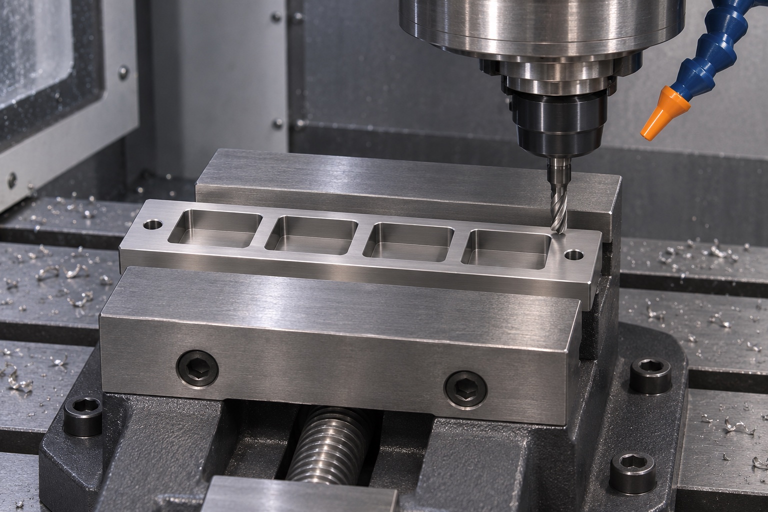
Rough the openings without weakening a contact wall
A candidate process faces a stable base, establishes the side reference and removes most pocket material while the rail remains well supported. Leave stock on the walls and seats for the final passes. When the rail is released, check for movement that could affect the final origin. Avoid using the thin webs between pockets as clamping surfaces. The illustrated CNC scene explains access, not a recommended cutter or machining parameter. Tooling and fixture loads would be developed for the actual stock, drawing and shop.
Finish the functional surfaces from the same origin
Where possible, finish the four openings and seats from a shared setup. If a separate operation forms the end holes or a relief, specify how the origin transfers and what must be checked again. Review the internal corner radius and the first usable contact height. A smooth pocket can still touch a surrogate at the wrong location. Do not blend functional edges after inspection to match a single sample. Any permitted rework should be recorded and the affected features checked against the drawing again.
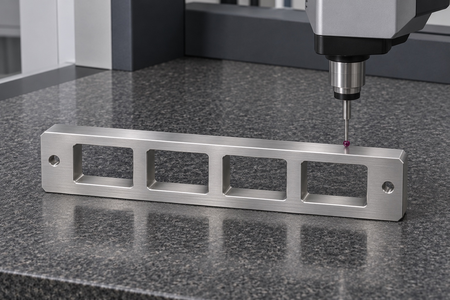
Inspect geometry by station and across the row
An example report would show the rail support, the reference features and the measurement zones for opening width, length, seat height and center position. Keep the four station results and the full span distinct. Do not substitute a single empty-cuvette trial for a coordinate check if the drawing calls for position measurements. The probe should not bridge a relief or use an entry chamfer as a wall. There are no dimension values, tolerance results or pass claims in the inspection image. It merely illustrates access to a relevant surface.
Use independent, identified surrogate placements
Place a rigid surrogate or an agreed empty cuvette at each station, without liquid and without powering equipment. Observe whether the intended contact is reached and whether the sample can be lifted out. Record the station, the surrogate ID and its orientation. If a reference is used at multiple pockets, observe each placement after complete removal. A fit check is specific to the chosen sample and setup. It does not establish analytical performance, sample transfer behavior, device compatibility or safe use of real biological specimens.
Diagnose a station mismatch before reworking
If one pocket is tight, compare the sample revision and measure the relevant wall or corner under the stated support. Look for debris and a raised edge. If tightness appears at all four stations, review the common reference, the support and the sample dimensions rather than enlarging every opening. Preserve the first inspection observations before taking corrective action. A repeat trial should use the same reference and orientation unless the change is intentional and recorded. This avoids mistaking a different sample for a successful geometry correction.
Keep finish and receiving cleanliness separate
An order would specify the surface condition and a method for removing loose machining residue. Inspect the seats, wall transitions and end holes after cleanup. Keep labels and adhesive off the contact regions. A visual inspection can identify chips and damage, but cannot demonstrate a validated cleaning process or a sterile state. If the receiving team requires a defined cleanliness condition, agree the requirements separately and state how it will be verified. The example is for a dry bench gauge, not a protocol for a working coagulation analyzer.
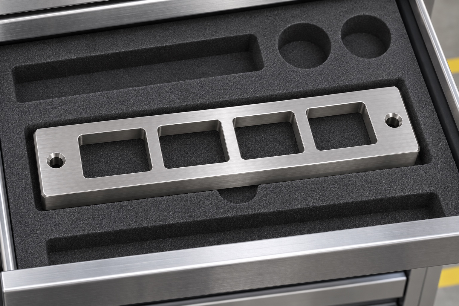
Protect the rail without loading the pockets
Support the rail at robust exterior regions in a fitted insert. Package hardware separately to avoid contact with pocket edges. Keep the revision and material lot tied to the inspection report. At receipt, check for impact, loose fragments or movement in the insert, then repeat any geometry check affected by visible damage. The illustration shows one possible physical protection arrangement only. It does not assert a cleanroom classification, validated storage life or sterile delivery. Inspection surrogates should be separately identified if they accompany the rail.
Deliver records limited to the manufacturing example
A real order would require controlled drawings, the approved surrogate, material and finish, station references, verification methods and packaging criteria. The shop can report the machined rail geometry and a separate bench observation under those conditions. Any use in a commercial analyzer and any validation of the clinical workflow remain with the equipment owner. No customer identity, delivery, acceptance or performance result is asserted here. The case illustrates how a four-station fixture can be manufactured and verified without extending a bench finding beyond its scope.
Manufacturer background reference: www.sysmex.com.
FAQ
Was the rail made for a named customer?
No. This is a representative example with illustrations. It reports no customer, delivery, certification, measurement or verified analytical performance.
What do the end holes do?
They retain the rail on a bench plate. They do not define precise location unless the released drawing intentionally assigns that function.
Can the pitch be checked with a single empty cuvette?
No. A single piece can reveal local fit. Measuring the position of each station relative to the defined reference is a separate task.
What should the report say about mounting?
It should state the support and fastening conditions, including whether the rail was measured free or installed on the defined test plate.
What should happen when one pocket binds?
Check the sample and station identity, edge condition, debris and measured geometry. Change the pocket only after the interference is identified and a correction approved.
Does a passing dry trial approve a clinical use?
No. It is limited to that surrogate and mechanical setup. Device approval and clinical testing are outside the scope.

tanghangyun@oemach.com