
Limit the example to a passive fixture
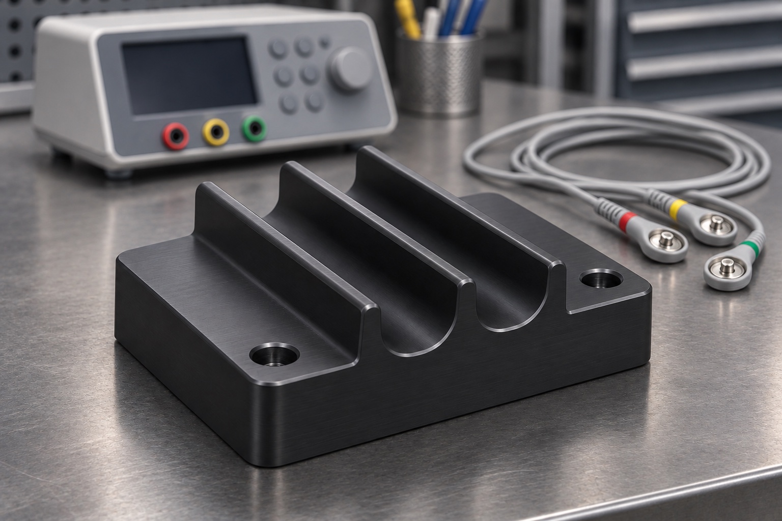
This representative CNC example considers a black-finished 6061 aluminum base with two rounded open-top channels and two recessed mounting holes. Its intended demonstration is to place inert cable surrogates on a bench and observe their clearances. The base is not an ECG adapter, conductor or approved accessory. The images are illustrative, not evidence of a customer delivery, qualification, compatibility or measured performance. The illustrated cable layout is not a wiring diagram or a procedure for connecting clinical equipment. No powered monitor, simulator measurement or patient use is required for the mechanical example.

Distinguish route from retention
The open channels provide space for two cable surrogates, and the recessed holes retain the base on a trial plate. The channels are not a clamp and the drawing would define whether either cable is permitted to contact the channel floor. The boot and jacket can have different clearance needs. Show the permitted path in plan and section so the operator can tell where a cable may be laid down and lifted out. If precise location of the base matters, specify a reference separate from the clearance holes or define an equivalent fixture setup.
Confirm the grade and finish before quoting
The material concept is 6061 aluminum with the temper and stock form to be specified. The black finish is only a proposed visual condition. An actual order would define the surface treatment, any masking and which measurements apply after finishing. Keep a material lot record and identify the finishing state on the inspection report. Do not infer electrical insulation or shielding from the look of an anodized part. The role of the base is mechanical, and compatibility with a real test bench depends on the complete approved configuration rather than color or grade alone.
Establish the mounting plane first
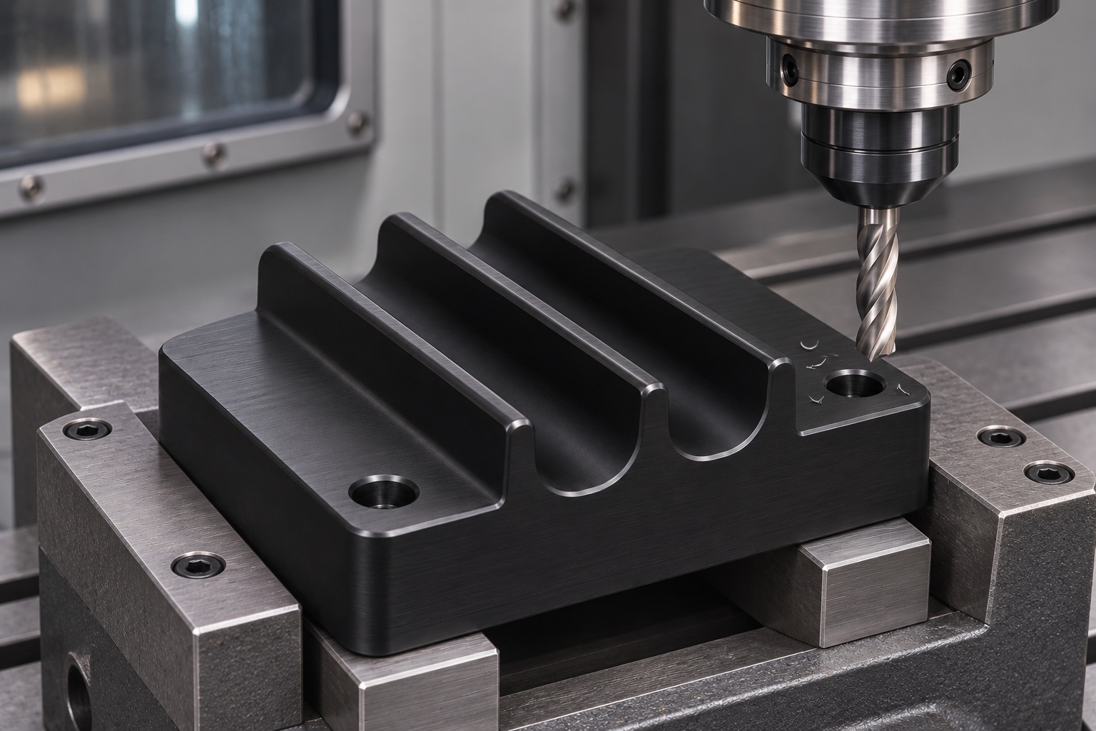
A candidate setup faces the bottom and establishes two side references on a stable blank. Hold the stock where the cutting loads can be supported without pulling the base into a different shape. Rough the two channels with allowance at the functional surfaces, then check the released part before finishing. If the part is repositioned to machine the holes, transfer the defined references and confirm the relevant features after the move. The CNC image illustrates access to an open profile, not an approved cutter, workholding procedure, feed or spindle speed.
Finish the open profiles and transitions
Finish the channel width and depth where the drawing permits the surrogate to sit. Review tool radii at the exits and avoid leaving a raised step in the path. Where the opening is designed to be rounded, measure the usable profile rather than treating a visual blend as acceptable. Protect adequate wall thickness around the mounting holes. Confirm that the final edge condition retains the intended clearance. If a drawing calls for a particular radius, define how it can be inspected and avoid uncontrolled polishing of a transition after the final check.
Keep screw heads clear of the routing zone
The mounting recesses can keep fastener heads below a designated surface, but only for specified hardware and seating conditions. Verify their depth and position independently from the channel geometry. An incorrect head or raised burr can interfere even when the holes are within their own size limits. Consider access for a driver in the intended fixture layout so installing the base does not require moving a cable in an unapproved way. The illustrated holes are examples of retaining features and do not imply a universal fit with any simulator or bench.
Measure a channel at several defined locations
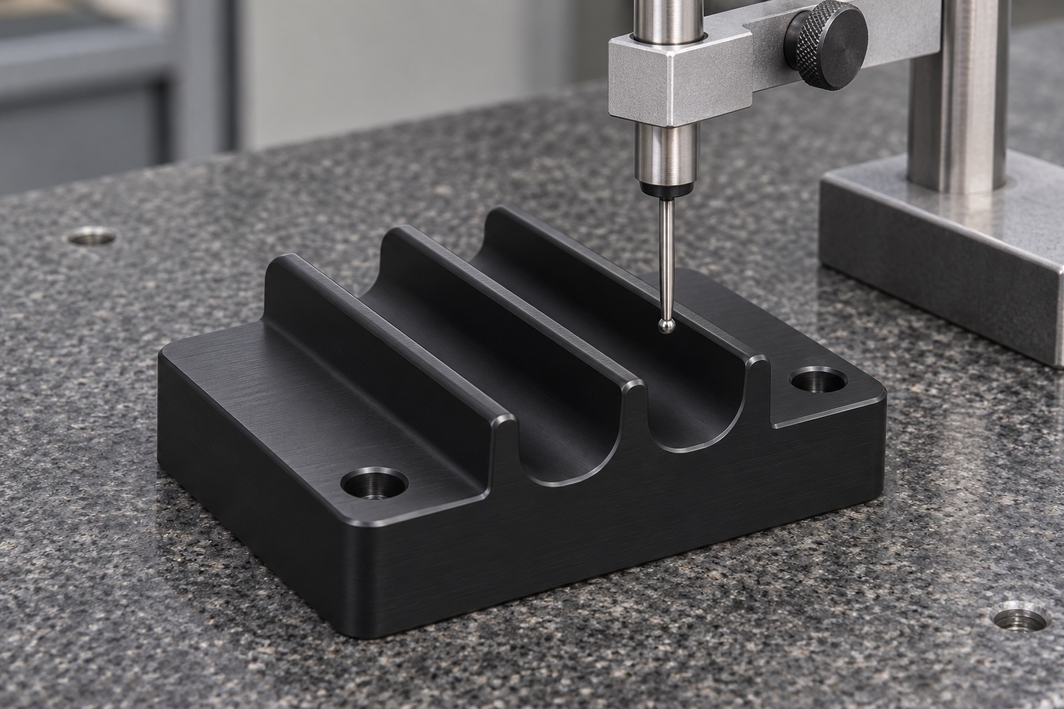
An example report could include the base condition, the two channel profiles and their position relative to the stated reference. Name the measuring stations and define whether the part is free or fixed to the trial plate. Verify exit transitions separately so a center reading does not hide an edge condition. Use an appropriate probe or profile method that does not bridge the concave floor. No readings, numerical tolerances or conforming results appear in the image. It shows where a geometry check might take place, not proof of an accepted fixture.
Check insertion and removal without power
Place identified inert surrogates in the channels according to the bench drawing. Note whether a boot can clear the end and whether the samples can be lifted without contacting a sharp edge or fastener. Document the position of any nearby boundary used in the trial. Do not change a connected cable or connect a clinical device during this exercise. A fit observation can identify an interference in a particular setup, but it does not test electrical performance, signal artifacts, cable fatigue or compliance. The equipment owner defines and performs any approved instrument checks separately.
Find the source of a routing mismatch
If one sample cannot sit in its intended position, compare the sample revision and boot shape with the envelope on the drawing. Check the channel width, the exit transition and fastener position independently. Inspect the base support for tilt or debris. Do not enlarge the channel before the cause is understood. If a geometry change is authorized, preserve the original observation and repeat the same check with the same references. This makes it possible to decide whether the correction fixed the intended issue or simply changed the overall bench layout.
Verify finish and identify the part
After the approved finish, inspect the channel transitions and any dimension affected by the treatment. Remove loose machining debris under the agreed method and keep labels off the mounting plane and cable contact areas. Identify the drawing revision, lot and finish condition on the report and package. A black finish is not evidence of electrical suitability or a controlled cleaning process. A visual check is useful for finding damage, debris and obvious edge defects, but it cannot replace an agreed dimensional check or a device-level inspection procedure.
Protect the open grooves during storage
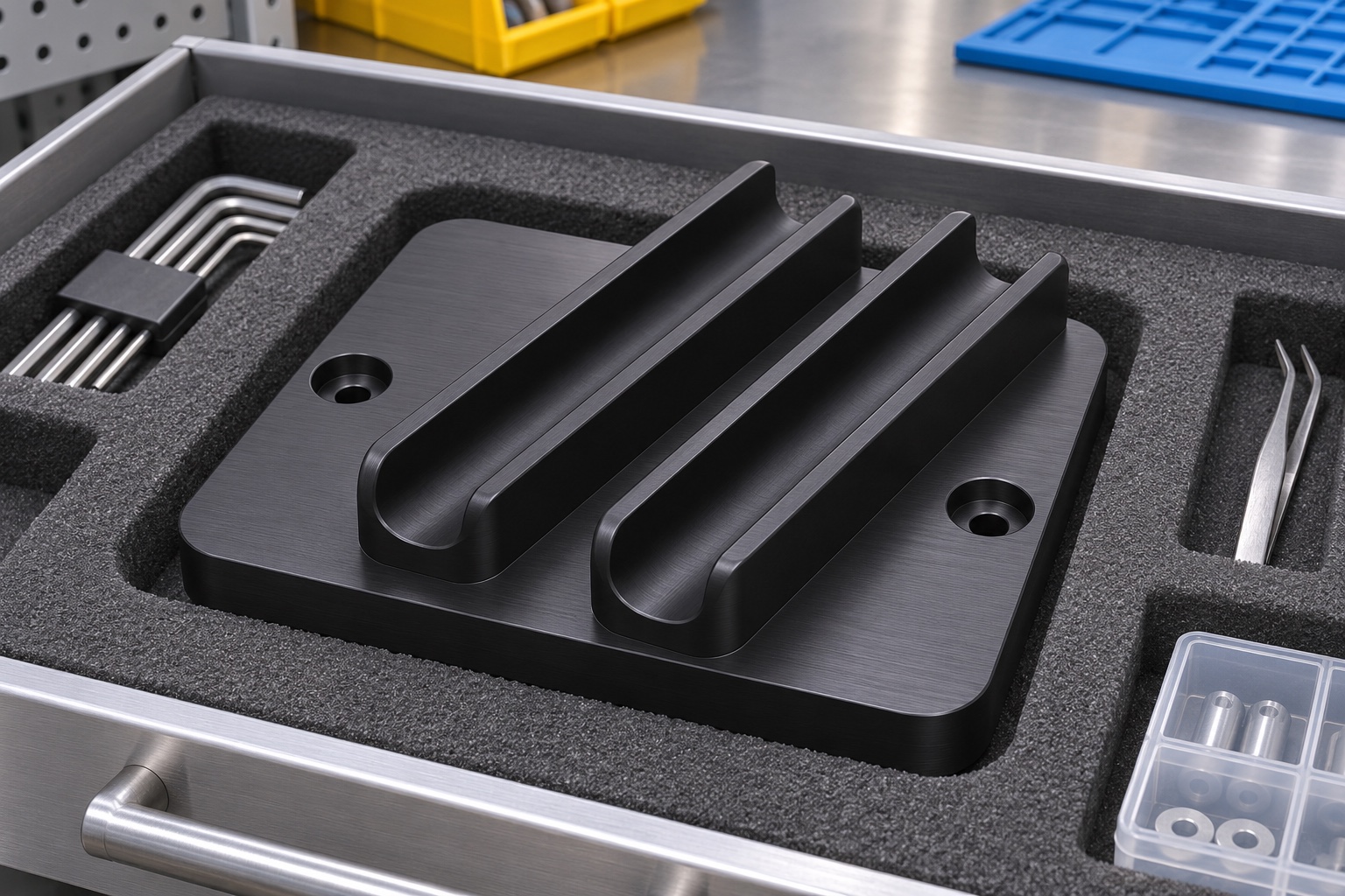
Support the base by robust exterior faces and keep hardware from rubbing the channel edges. An insert can restrain movement without pressing into a groove or loading a thin wall. Maintain the inspection record with the part revision and note if any surrogate is packed separately. At receipt, check the edges and mounting plane after a visible impact, then repeat the relevant geometry or layout observations. The illustration shows ordinary protection for a shop fixture. It is not a cleanroom, sterile, packaging validation or storage life claim.
Request evidence limited to the actual scope
A real manufacturing order would need the current drawing, material and finish, surrogate envelope, inspection states and packaging. The supplier would report dimensional evidence and separately document the passive layout trial if requested. Approval of a cable routing arrangement around a real test instrument belongs to the responsible equipment owner. This example does not assert that any specific customer received a part or that a product passed a test. It demonstrates how a machined fixture can be evaluated on its own terms before any higher-level equipment work is considered.
Manufacturer background reference: www.flukebiomedical.com.
FAQ
Is this a delivered or approved part?
No. It is a representative CNC case with illustrations. It is not a delivered customer part, electrical accessory or clinical approval.
What are the two grooves used for?
They provide separate paths for cable surrogates on an unpowered bench. They are not intended to grip or electrically connect the cables.
Why recess the mounting holes?
An approved fastener head can sit below a designated clearance surface. The intended hardware and head position must be confirmed on the actual drawing.
Does black finishing provide electrical isolation?
No isolation claim follows from the finish. Electrical properties and any required separation must be established for the approved equipment setup.
Can the trial confirm ECG signal quality?
No. It can reveal mechanical clearance or handling issues with inert surrogates, not signal integrity, monitor function or patient safety.
How is a suspected burr handled?
Identify its location and effect against the drawing, perform only approved correction, then recheck the affected geometry under the defined conditions.

tanghangyun@oemach.com