
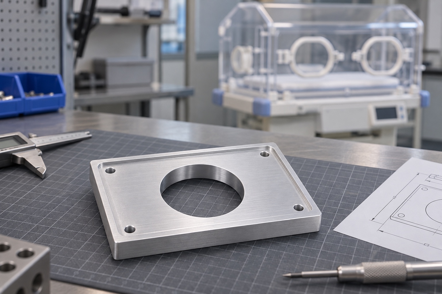
Set the scope of the demonstration
This representative CNC example considers a rectangular 6061 aluminum bench plate with a central round opening, a shallow perimeter step and four corner mounting holes. An inert sensor envelope would be used to review clearance on a development bench. The plate is not an incubator replacement part or an approved adapter. No patient, customer delivery, measured result or environmental performance is reported. The pictures illustrate possible manufacturing and inspection approaches; the approved interface geometry, fastening conditions and device design are deliberately not inferred from the images or the manufacturer background reference.

Map the mechanical interfaces
The concept has a base seating face, a perimeter transition and a through aperture. The example uses the aperture as clearance for a dummy housing, not as a seal or a sensor datum. The final design would specify where the surrogate flange seats and which areas must remain clear during insertion. The four mounting holes retain the plate in the bench frame. Define a separate lateral reference if the order needs consistent position after removal; do not assume loose screws can supply it. The setup must not include a clinical device or connected sensor.
Establish the stock and the final state
Specify 6061 with the required temper, stock form and material documentation. Capture the lot before machining and keep that identity with the finished sample. The example shows a bare-looking metallic finish, which does not establish alloy or coating. If later samples have a surface treatment, confirm the acceptance condition and which features need remeasurement. Review the actual mounting thickness and the expected contact regions before assigning a machining allowance. A metal choice for the bench plate does not imply suitability for humidity exposure, cleaning agents or service in a patient compartment.
Machine a stable base before opening the center
A candidate process faces the mounting surface and establishes side references with the blank supported on a stable fixture. Rough the opening and leave material at the shoulder and step. Once the center is open, release the part and check whether it moves enough to affect the finish setup. Keep the handling method consistent so a flexible region is not squeezed differently on each pass. The picture is a generic CNC scene; it does not represent qualified workholding, a specified cutter or a manufacturing parameter for a real incubator component.
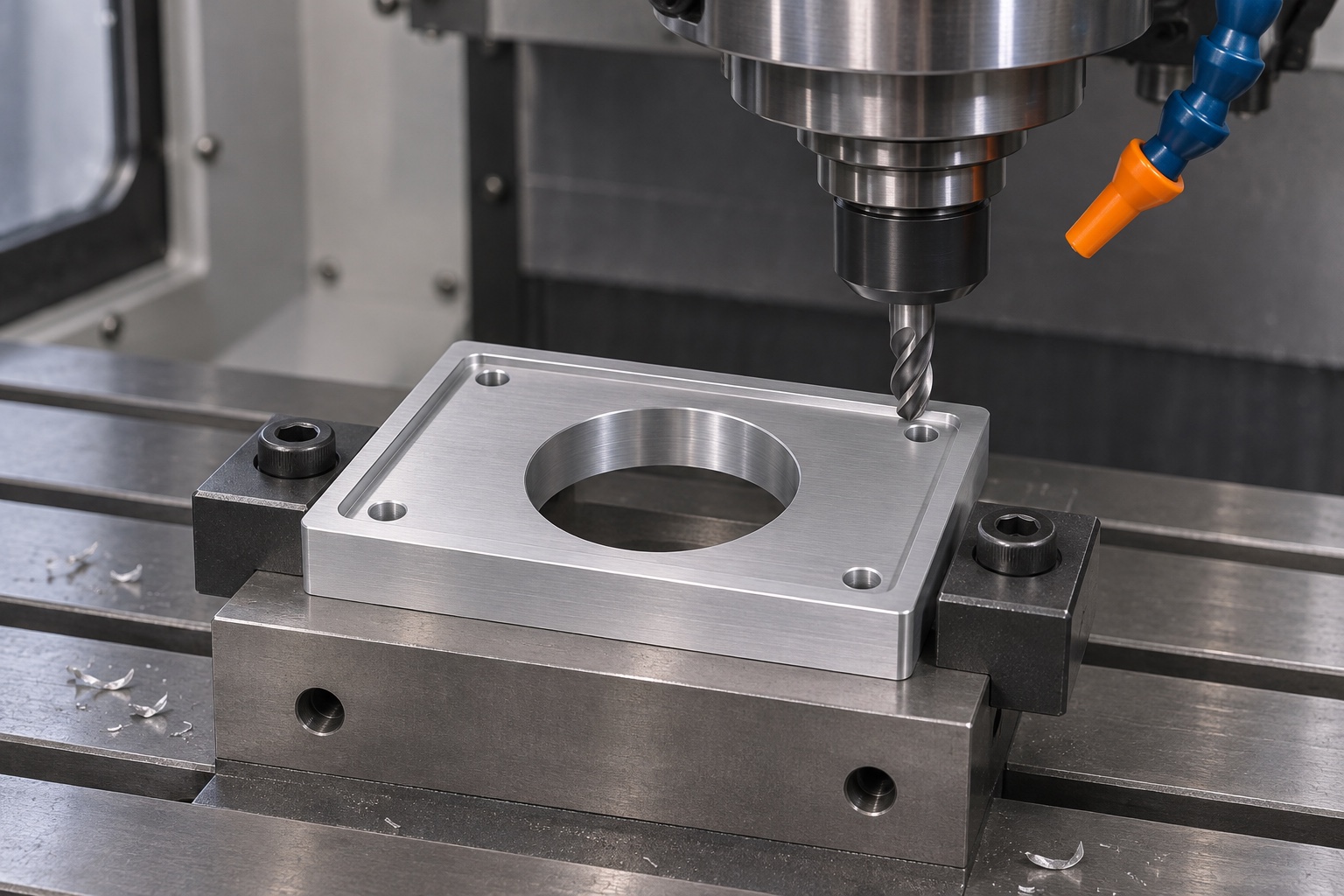
Finish the perimeter step without hiding warp
Finish the step relative to the stated base and locate the usable contact area away from the transition radius. If the drawing allows a narrow relief, confirm that it does not enter a seat or obstruct access. Inspect in the stated condition, especially if clamping could flatten an unsupported corner. Record changes found after release rather than relying on an in-process reading under clamp load. A condition found in a mounted setup should be labeled as such and tied to the exact bench frame and fastener arrangement used in the check.
Verify opening and hole features independently
Finish the aperture from a reproducible origin and machine the four holes to the approved pattern. If the two operations cannot share a setup, define how the origin is carried over. A hole that accepts a screw may still be out of position relative to the opening. The trial drawing should describe which axis or edges establish the reference and which features are merely for retention. Inspect aperture entry and exit edges separately so a burr does not give the impression of a small bore or prevent seating even when diameter meets the drawing.
Measure on the defined supports
An example geometry report could show the base condition, step height at each named station, the usable aperture profile and the mounting-hole relationship. Specify where to probe to avoid the edge break. The report would record whether the plate was supported at defined points or mounted to a bench frame. Give the receiving team a sketch and mark how a repeat measurement is aligned. Do not infer concentricity, flatness or clearance from the illustration. No tolerance, numerical reading or passing inspection is represented by the photograph of a possible setup.
Check a dummy housing without powering equipment
The engineering trial would insert a rigid surrogate from the intended direction and observe seating and clearance. Use a defined surrogate revision and record any features that contact earlier than expected. Separate the orientation condition from the final position so an obstruction during removal is not hidden. Leave all electrical connections out of the trial. A successful insertion says only that this surrogate fits this documented bench arrangement. It does not establish temperature response, sensor calibration, humidity control, compatibility with a commercial incubator or an approved service procedure.
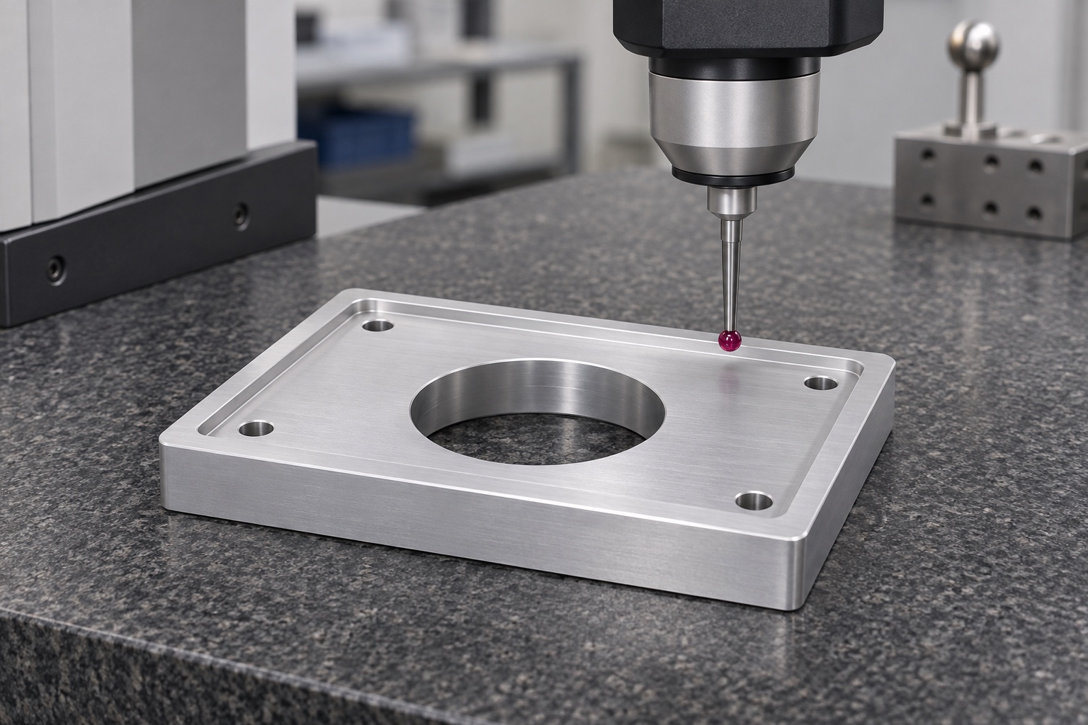
Diagnose a tight fit before removing material
If the dummy housing does not seat, compare its revision, the plate support, the aperture and the nearest step to the nominal drawing. Look for a protruding fastener, debris or an edge condition before attributing the problem to diameter. An authorized change should have a stated reason and a repeatable verification plan. Store the original measurements with the correction record. Otherwise, a later bench fit could appear successful because a different dummy or bench frame was used. Neither a corrected sample nor this illustrative case establishes suitability for a real medical device.
Define final cleanliness and part identity
Remove loose machining debris under the agreed process and check the aperture, mounting holes and step after cleaning. Keep adhesive labels off seating and inspection faces. The report should identify the drawing revision, material lot, finish and any affected features after rework. Visual appearance does not prove controlled contamination or compatibility with a cleaning agent. If the order requires packaging or handling beyond ordinary shop protection, specify and verify those requirements independently. This representative example does not claim clinical cleaning, disinfection or sterility at any stage of the work.
Use protective packaging without distorting the plate
The packaging concept supports exterior regions rather than pressing against the stepped reference. Loose hardware should be kept away from the opening and contact zones. Link the package to the inspection report and stock lot. At receipt, examine the perimeter and aperture for damage and inspect the insert for movement or compression before a trial. If the package has been dropped, repeat the affected checks under the prescribed support condition. The illustrated insert provides ordinary physical protection and does not establish a sterile barrier, classified cleanliness or storage qualification.
List the evidence for a real manufacturing order
An actual order would define the controlled plate and surrogate drawings, material and surface condition, reference frame, inspection stations and receiving criteria. The machining supplier can provide geometry and a separate bench fit record within that scope. The equipment owner remains responsible for any sensor placement, environmental testing and approval of the complete incubator. This example reports no actual customer, specification compliance, clinical use or performance result. Its value is a documented relationship between a simple part, the reference surfaces used to check it and the exact question the mechanical trial can answer.
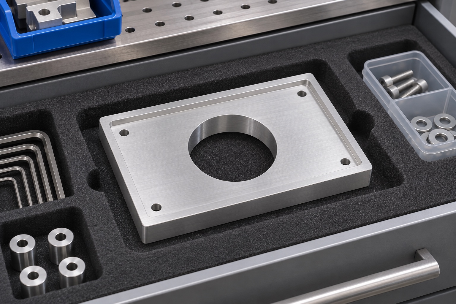
Manufacturer background reference: www.draeger.com.
FAQ
Was this plate delivered to a customer?
No. It is a representative CNC manufacturing example. The images do not establish a delivery, certification, device compatibility or measured result.
What does the circular opening do?
It provides clearance for a dummy sensor envelope in the concept. It is not a fluid, air or electrical interface and has no claimed seal function.
What is the purpose of the perimeter step?
It represents a controlled mechanical interface to the bench frame. Its relationship to the base should be checked at specified locations.
Do the corner holes establish precision location?
Not in this example. They retain the plate. A defined locating feature or measuring origin is required if lateral position must repeat.
Can the fixture be installed on an incubator?
This example does not authorize installation. Any real service or design change requires the device owner's approved parts, drawings and procedures.
What does a trial report contain?
The surrogate revision, orientation, support, contact observations and open issues. A mechanical fit report does not validate the sensor or incubator.

tanghangyun@oemach.com