
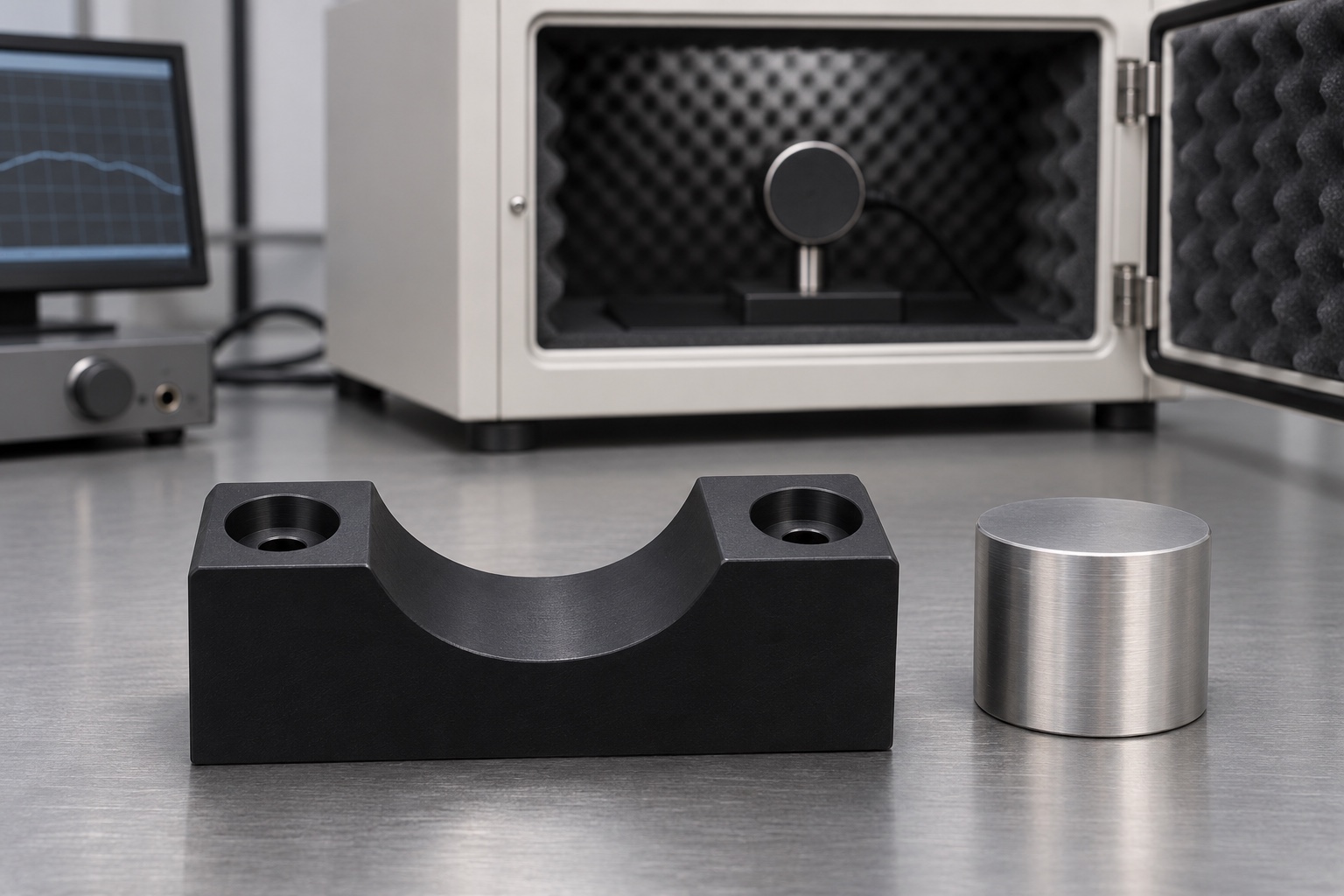
Keep the saddle out of the acoustic path
Hearing instrument test equipment can use a coupler as part of its measurement configuration. An external mechanical saddle can help position the coupler body on a bench, but it is not the coupler, the calibrated cavity or the acoustic seal. In the concept considered here, the saddle only contacts specified exterior surfaces. It should not constrain the acoustic port, alter an approved connection or support clinical interpretation. Start with a drawing of the equipment arrangement and get the owner to identify areas that must remain open and untouched.

Locate only where the coupler body permits
A shallow cylindrical cradle may suit a smooth outer shell, but connectors, seams and local shape changes can create unplanned contacts. Specify which segment of the shell is supported and leave clearance to other details. If a feature is sensitive to side load, the fixture should not push against it just because it is convenient to reach. An axial reference or stop may be needed, but it must not be the connector or acoustic entrance unless the approved design explicitly says so. Keep support, location and retention separate.
Decide whether the body must be removable
A removable support should allow a user to lower and lift the body without crossing a cable or loading a connector sideways. The final seated position alone does not describe that motion. Sketch the insertion path and define any required orientation before detailing the cradle. If cables are connected in the intended configuration, confirm that the path and supports do not force them into a tight bend. Do not assume a polymer block protects the entire measurement chain or changes which handling rules apply to the instrument.
Create references that can be reconstructed
Use a base face and suitable side features to relate the cradle to the test plate, and identify whether a screw only retains the block or also locates it. Two clearance holes should not be assumed to provide precise lateral positioning. The drawing can specify an axis location and the region over which the support acts. If a small saddle is used with a second support, define the relationship between the two rather than independently targeting a height with no common reference. That relationship may be more important than the outline size.
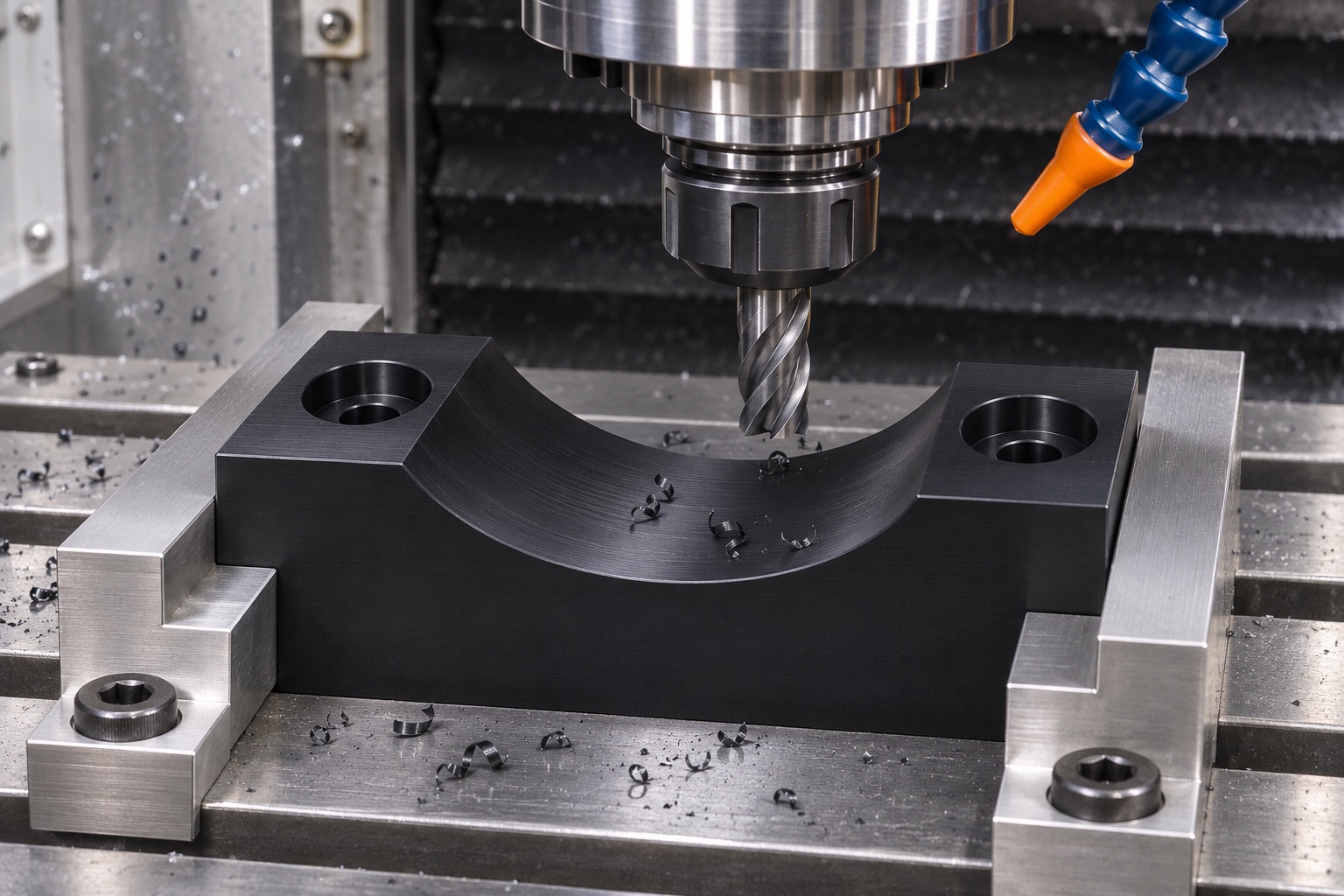
Consider contact force and edge geometry
The support should contact the intended outer segment without making a seam, edge or local projection carry load. Round or relieve nonfunctional transitions where the drawing permits, but do not change the functional cradle after measurement. A body that appears centered under its own weight may shift when a cable is pulled or during installation. Do not infer a permissible load from a successful dry fit. If the equipment owner specifies a contact pad or liner, include its dimensions and final condition in the installed inspection.
Specify the exact polymer and final state
A machinable engineering polymer such as POM-C can be considered for a prototype saddle, but the specific grade and stock form matter. Record environmental and cleaning requirements instead of assuming all black polymer parts behave the same way. Identify whether labels or adhesives are allowed, and keep them away from the reference surfaces. Any claim about electrical, chemical or acoustic behavior requires evidence appropriate to the complete intended setup. The images and the mechanical drawing are not evidence that the material suits a calibrated measurement path.
Plan machining around the cradle and the base
Establish a stable base and supporting stock before roughing the cradle. Choose a method that gives access to the full usable surface and does not leave a ridge at the transition. Avoid clamping force that changes the shape measured after release. Locate holes from the drawing references, and review countersink or counterbore geometry for the intended hardware. If cutting releases stress in the blank, inspect it in the agreed support condition before the final pass. Document the tool-access constraints instead of treating the illustrative photograph as a work instruction.
Inspect an axis without reading the wrong surface
A defined cylindrical master can help relate seating to the base if its diameter and support conditions are specified. The master represents that one geometry, not every shell size. A coordinate check of the cradle and a seating check with the master address different questions. When measuring the top of a master pin, record its diameter and verify that it rests on the expected contacts. Compare readings at several longitudinal stations if the drawing controls axis direction. A reading at the very edge of a relief does not represent the usable cradle.
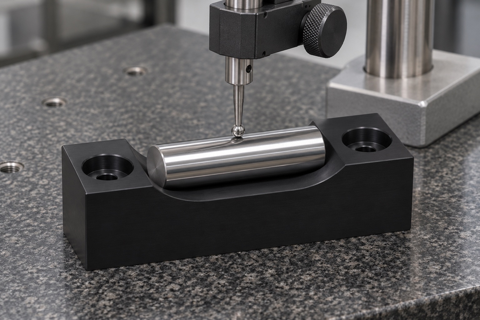
Isolate changes in a bench trial
Use a representative inert shell or gauge for initial mechanical trials. Remove and reseat it under a documented setup and note whether movement follows the part, the support or cable handling. If the bench layout uses a second support, compare each support independently before interpreting a combined result. A reproducible mechanical height does not prove that the acoustic connection remains valid. Device verification and calibration should follow the equipment owner's approved methods and should not be replaced by an unofficial cradle test or extrapolated from an illustration.
Protect the cradle and mounting plane
A loose chip in the cradle may alter seating, while a raised edge at a mounting hole can change the block attitude. Inspect both regions under an agreed edge and debris criterion. Remove chips after machining without polishing or scraping away a defined contact. If the inspection requires a controlled state after cleaning, document that state and keep it separate from any claim about decontamination. The support is intended to touch an external housing only; nothing in the illustrated bench setup indicates sterile or clinical handling.
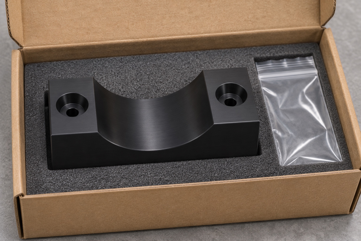
Preserve part identity between uses
Package the support so the curved contact region is free from impact and abrasion. Locate identification where it will not create a raised contact on the base or cradle. If the part is maintained as a fixture, provide a clear way to distinguish a verified revision from an uninspected spare. Check the package and the geometry after a drop or visible damage before using the support as a reference. A fitted insert and protective bag prevent some shipping damage but do not establish cleanliness levels or a service life.
Define the evidence the machine shop can provide
Send the support drawing, permitted shell contact area, clearance requirements, grade, intended bench state and inspection plan. Ask for separate results for cradle geometry, mounting references and any mechanical seating trial. Leave the acoustic measurement, coupler performance, and approved device setup with the responsible equipment team. A good handover lets another person reproduce the bench support and identify what remains to be validated. It does not treat repeatable mechanical location as a proxy for an accepted or calibrated acoustic measurement.
Manufacturer background reference: grason-stadler.com.
FAQ
Is the support an acoustic coupler?
No. It supports an exterior body in a defined setup and does not establish cavity volume, sealing, acoustic response or calibration.
Why use a cylindrical master?
It can make seating and height checks reproducible if its size and condition are known. The drawing should still specify the actual cradle geometry and permitted contact areas.
Can cable routing change the position?
It can introduce force or obstruct insertion. Evaluate routing with the equipment owner, without changing any approved connection or assuming the fixture corrects a cable-induced error.
Should the mounting screws define the datum?
Only if the drawing deliberately assigns that role and specifies the corresponding features. Clearance holes ordinarily retain the support without guaranteeing lateral registration.
Does POM-C guarantee acceptable acoustic behavior?
No. The grade is a mechanical design candidate. Acoustic behavior depends on the approved measurement configuration, and the saddle must not modify the acoustic path.
Can the saddle be used to calibrate hearing instruments?
No. The example only addresses a mechanical support. Calibration and interpretation require the approved equipment, configuration and procedures.

tanghangyun@oemach.com