
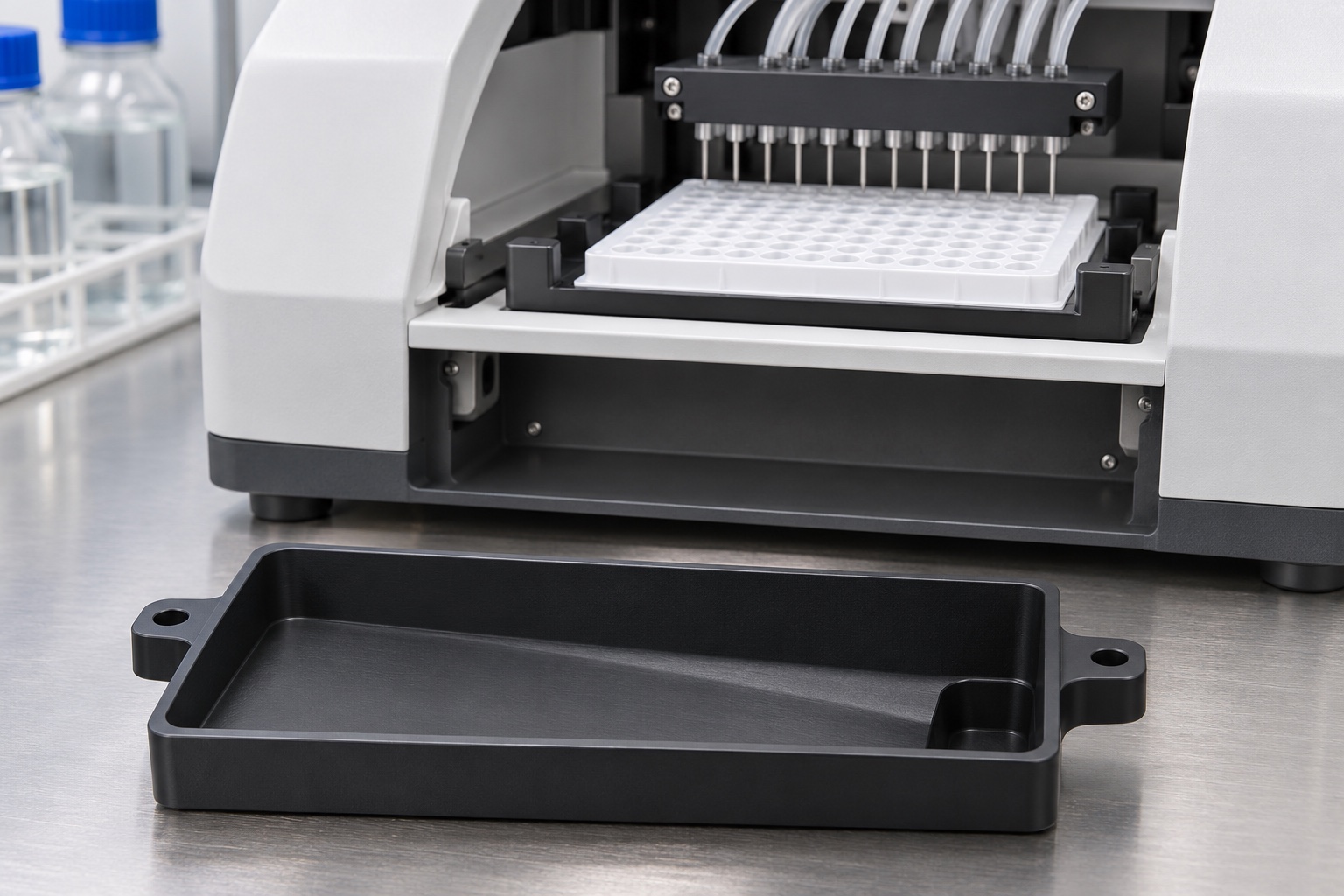
Distinguish drip collection from the wash system
A diagnostic microplate washer uses dedicated fluid-handling components for its intended process. A removable tray below a service area can be designed to collect incidental drips, but it does not replace the intended waste path, bottle or overflow controls. Start by defining where drips can originate and whether the tray is present during operation, service or both. This article concerns secondary collection geometry in a generic bench concept. It is not a retrofit instruction for an existing washer or a claim about assay performance.

Draw the installed orientation
A slope marked on a part drawing is only useful if the part is installed in the intended attitude. Relate the floor to the rail or seating plane. Identify the intended low area, the usable collection region and the clearance needed to remove the tray. If the machine sits on adjustable feet, establish the expected installation envelope with the equipment owner. A floor that looks sloped on the bench may leave an unintended pool after the tray is seated at a different pitch.
Specify function rather than an ornamental slope
Define where fluid is intended to collect and which edges must remain high relative to that region. Where the tray has no drain, a low pocket makes visual inspection or emptying easier but cannot prevent overflow by itself. The design should specify the expected liquid and capacity criteria at the system level. A geometric floor gradient does not determine every behavior: surface condition, a meniscus, foaming and a moved tray can change the observed result. Separate those effects in the trial plan.
Check the motion envelope with the tray inserted
Test for interference with adjacent panels, tubing, an access door and any sliding hardware. The clearance that matters is the full removal and insertion path, including the hand access approved by the owner. A raised rim can strike a panel when the tray is tilted even if it clears in the seated position. Define which features support the tray and which are only handles or guides. The part supplier needs a reliable installed envelope or a representative test fixture to check those interactions.
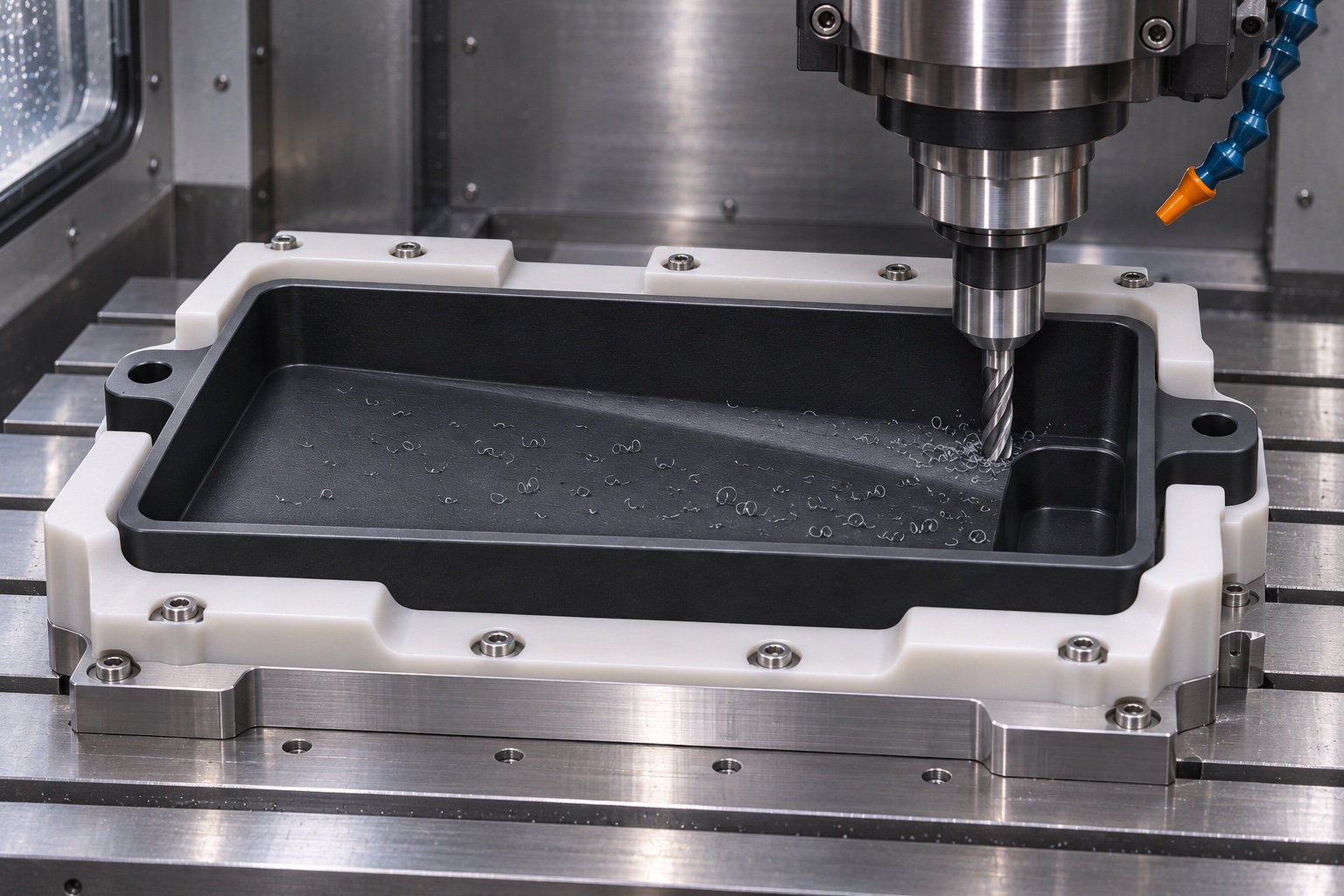
Choose polymer against the intended chemistry
Polypropylene may be a candidate for a prototype, but specifying the resin family alone does not establish chemical compatibility. Agree the actual grade, fluid contact, temperature and exposure duration. Consider cleaners and drying methods as separate exposures. The design owner should decide whether swelling, surface damage or absorbed residue must be assessed under a defined test. A dark material can also hide some deposits that would be visible on a light surface. Do not infer compatibility or cleanliness from the appearance of an illustration.
Control movement during pocket milling
Removing a large pocket changes the stiffness of the blank. Support the stock near the cutting loads without squeezing the finished rim out of shape. A candidate route establishes the underside and reference edges, roughs the cavity, and releases the blank to assess movement before a floor finish pass. Keep the usable volume and the outside support surfaces separate when allowing stock. The final process, including cooling and chip control, should be established on the actual grade, machine and trial pieces.
Design internal corners for access
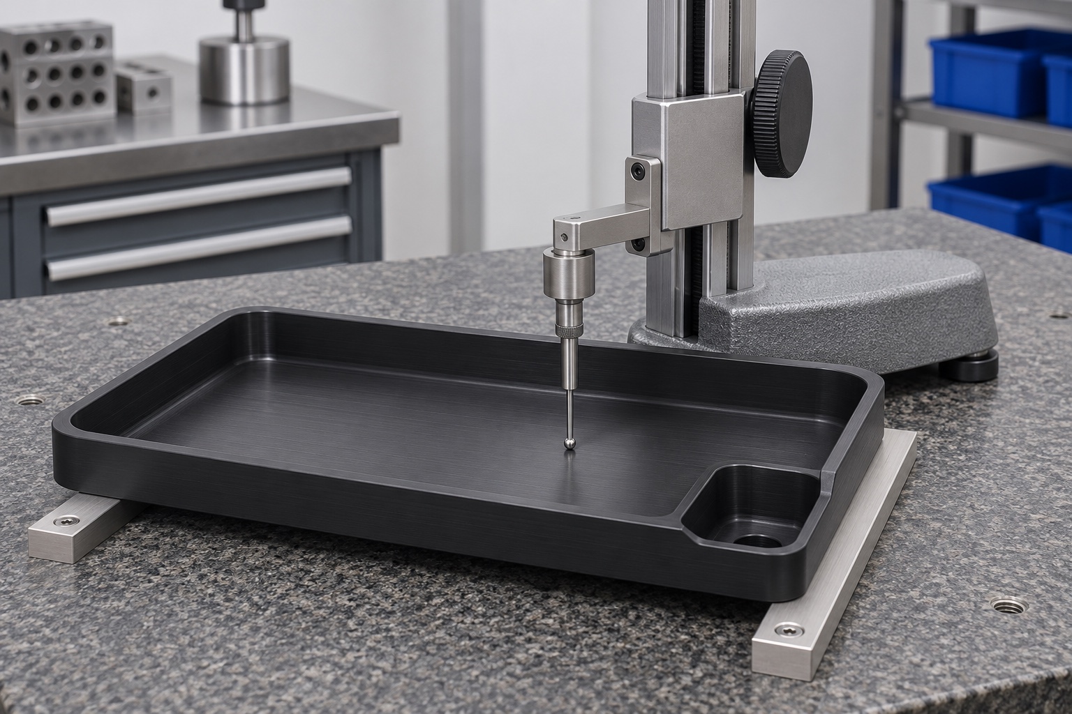
A radius can make a pocket easier to machine and inspect, but only if it leaves the required collection volume and permits access for the approved cleaning method. A deep small corner may become the lowest point even when it was intended as a tool clearance detail. Put an accessible measuring point near the collection pocket without assuming a probe can enter every corner. Discuss whether the drawing should define a floor profile, local height stations or both, and record which regions are excluded from inspection.
For example, mark a high station near the drip entry, two intermediate stations and a low station beside the collection pocket. Keep the points far enough from radii that a probe can reach them without touching the wall. Number them on a simple inspection sketch and align the sketch with the rail direction. This is more useful than reporting the depth at whichever corner is easiest to reach. If the station readings and the bench collection observation disagree, check installed attitude and surface condition before changing the proposed floor geometry.
Measure with the actual support in mind
Use the defined rail supports or a representative seat so that measurement can be related to the installed orientation. Check several heights across the floor rather than reporting one diagonal value. Inspect the rim and support ears in the condition specified by the drawing. A forceful clamp can temporarily change a thin polymer part, while an unsupported corner may sag under a probe. Report any contact force or support condition that materially changes the result, and keep free-state and installed readings distinct.
Use a bench collection trial only within its scope
A controlled trial with a safe surrogate liquid can show where drips collect in a representative bench setup. Document liquid, quantity, release positions and support orientation; observe standing liquid and removal handling separately. If the design relies on cleaning or spill containment, the owner must specify separate tests with suitable controls. A convenient water demonstration does not represent every cleaning agent, waste mixture or temperature. It cannot establish fault containment, cleanability or any safety claim for the complete equipment.
Inspect the rim, floor and removal features separately
A burr on the support ears may shift the tray even though it does not touch liquid. A chip or scratch inside the tray may affect drainage or cleaning. Put different acceptance descriptions on those regions and specify how debris is removed after final machining. Avoid aggressive edge cleanup that lowers a containment rim or leaves loose polymer strands. When a sample rocks, establish whether the source is a changed rail, distortion in the tray or a raised edge before reworking any surface.
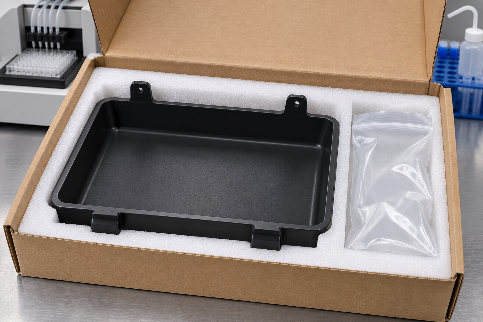
Protect against distortion in shipping
Place supports under robust outer areas and avoid stacking force across the thin floor. Keep the rim away from abrasive inserts or loose items. An approved bag can separate dust from the cavity if required, and any label should stay outside the collection area. Check that the package does not flex the tray into a different shape during storage or transport. This is physical protection only. Controlled cleanliness, decontamination, sterile packaging and shelf life would each require their own definition and evidence.
Give suppliers a checkable order
Send the design revision, grade, installed orientation, defined support surfaces, floor and rim checkpoints, and receiving requirements. Include separate assignments for geometry, bench collection and equipment integration. A measurement report should identify the part lot and say whether the tray was free or installed. Keep any open questions about chemicals, actual waste, approved cleaning or fault response with the device owner. This prevents a successful CNC inspection from being interpreted as evidence about the performance of an entire washer.
Manufacturer background reference: www.tecan.com.
FAQ
Is a secondary tray a substitute for the waste bottle?
No. It is a separate component for defined incidental collection. The original waste handling, level monitoring and fault response remain governed by the equipment design and its approved operating instructions.
Why specify a support plane for the floor slope?
The installed support determines which point is actually lowest. A tray measured on a different plane may appear to have the intended slope without collecting fluid at the desired point in the assembly.
Can a water trial prove chemical compatibility?
No. It can help observe geometry and collection in the stated setup. Compatibility requires the actual grade, intended liquids, cleaning conditions and an approved test plan.
How can machining affect floor flatness or slope?
Removing pocket material changes stiffness and may release stock stress. Verify the part after release and document the support and probing conditions so temporary clamping does not conceal distortion.
Should the rim and ears have the same inspection criteria?
Not necessarily. Rim height and edge condition can affect collection and handling, while support ears can affect the installed attitude. Use separate checks for features with different functions.
Is a protective bag enough to claim clean delivery?
No. The bag can reduce handling contamination and abrasion. Any clean or sterile delivery claim needs its own requirements and evidence; no such classification follows from ordinary protective packaging.

tanghangyun@oemach.com