
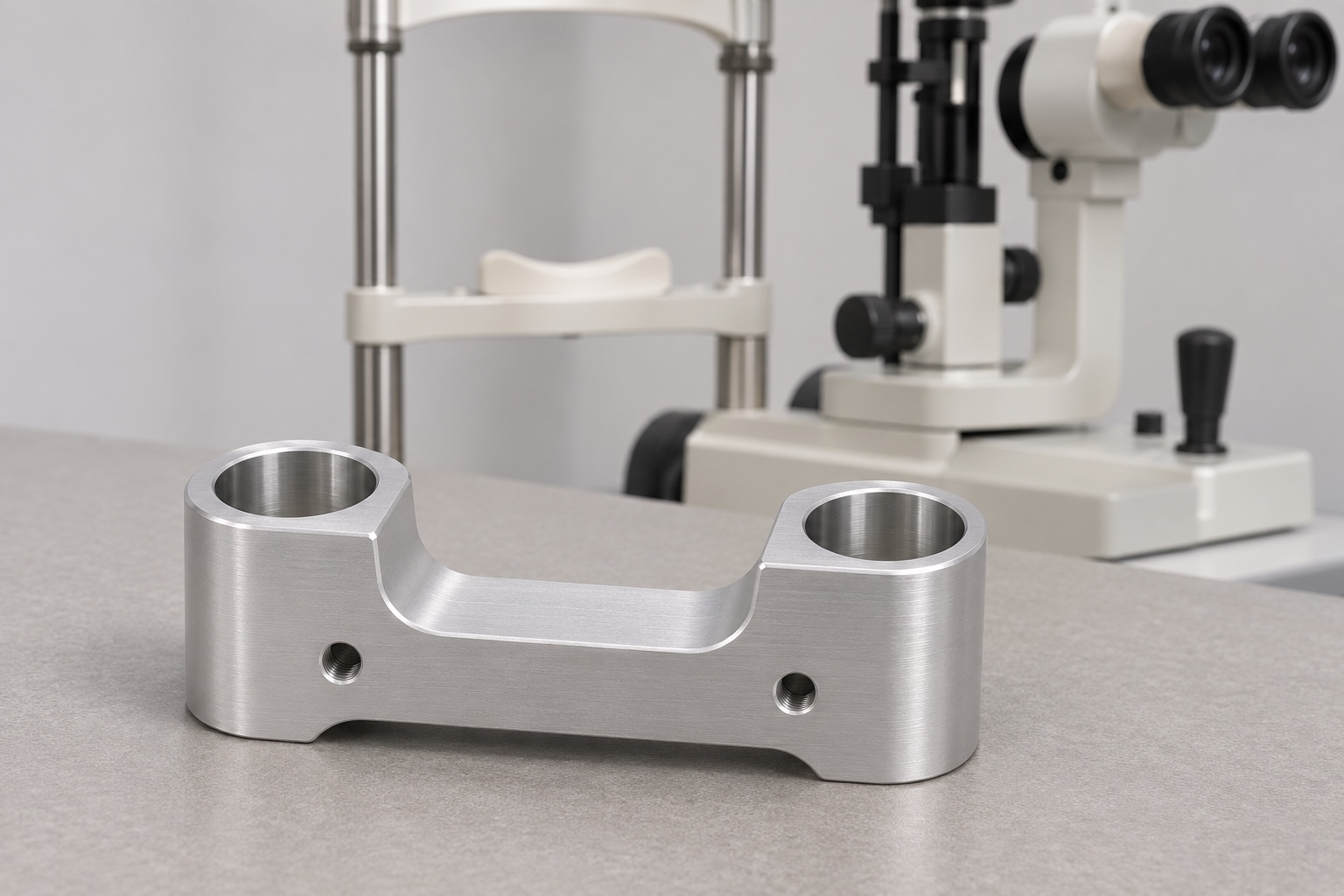
A guide carriage rather than a complete chinrest
This representative manufacturing example concerns a compact 6061 aluminum bridge for an ophthalmic support assembly. Each end has a vertical guide bore and the front has two attachment holes. A shallow central relief leaves access around the bracket. The carriage is not intended to contact the patient directly in this concept. The example illustrates part manufacture and bench fit planning, not a real customer order, a compatible spare part for a named device, a load rating or a verified clinical result.

Identify which features locate and which fasten
The two bores interact with the specified guide posts. The attachment face transfers movement to a separate support bracket. The two front holes are treated as retention unless a released design explicitly gives them a locating function. That distinction affects both the datum scheme and the test fixture. Establish a primary seat for the bracket and a reproducible guide reference. Leave sufficient relief around adjacent geometry so the bridge does not falsely seat against a boss or corner in the mating bracket.
Keep the blank and the final state traceable
The candidate material is 6061 with a temper and stock form to be specified by the drawing. The illustration does not establish alloy, temper or any finish. Verify material documentation against the actual blank and record its lot before cutting. A production drawing would specify a final surface condition, including any masked surfaces and their boundaries. If plain aluminum is only the prototype condition, the finished configuration requires its own inspection, not acceptance based on the dimensions of a bare trial part.
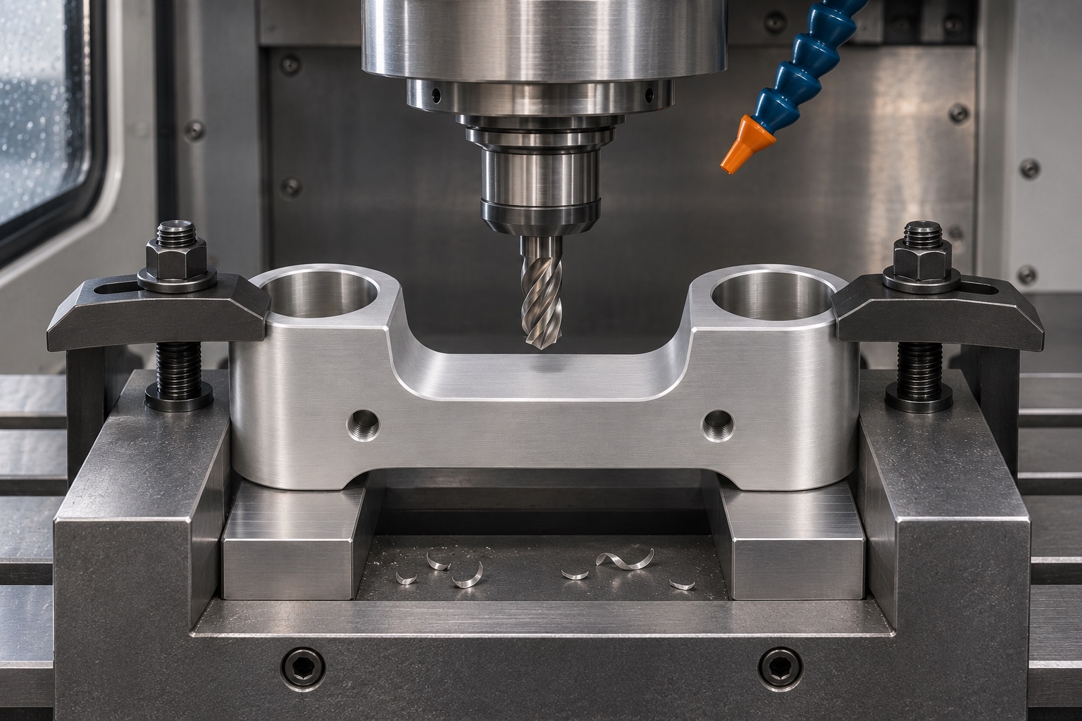
Rough the form without pinching the ears
A first operation can establish a broad reference face, rough the outside profile and remove most of the central relief stock. Hold the stiffer portion of the blank on stable supports. If clamping squeezes the thin regions around the bores, the relaxed part can differ from the machined shape in the fixture. Leave appropriate finish allowance after roughing and check how the blank reseats. The pictured tool and workholding are explanatory, not a cutting program or process approved for any specific part.
Finish the guide geometry together where possible
After the rough form has stabilized for the agreed conditions, one candidate setup finishes both bores from the same reference. Select an approach that can control size and form at the engagement depth, not only at the entrance. Check the remaining wall around each ear before choosing a cutting method. If separate setups are necessary, identify how the reference will transfer and how the second bore will be related to the first. Confirm that surface cleanup does not blend away the effective bore length.
Relate the front face to the motion direction
The front face and two holes should be verified with respect to the guide references called out by the design. A bracket that appears flush while unloaded can apply a side force to the carriage when tightened. Inspect the face and its contact regions, and compare bracket condition separately if the installed unit behaves differently. The central relief should clear the bracket through the planned movement. It is not a second locating face unless the approved drawing explicitly requires it.
Inspect bore size, form and spacing
Use an appropriate method for diameter at defined depths and measure the axis relationship with a setup that references the relevant seat or guide interface. A plug may quickly screen a bore, but it does not locate the pair relative to each other. Document support, measurement positions, fixture condition and any inserts. If inspection uses a coordinate machine, the probing strategy should represent the engagement area and avoid edge breaks. No dimensions or inspection results are reported in this representative case.
A first-article worksheet could show the two ears and number the bore measurement stations from the same end. Add fields for bracket mounted or removed and for the trial post set. Use the same numbering on the drawing and the receiving form, especially if the front holes make the part appear symmetrical from some directions. If the bench fit is unacceptable, the worksheet should let the reviewer trace the observation to a specific station and condition. It should not assign an automatic cause, such as bore misalignment, without a corresponding measurement.
Run a controlled dry fit with surrogate posts
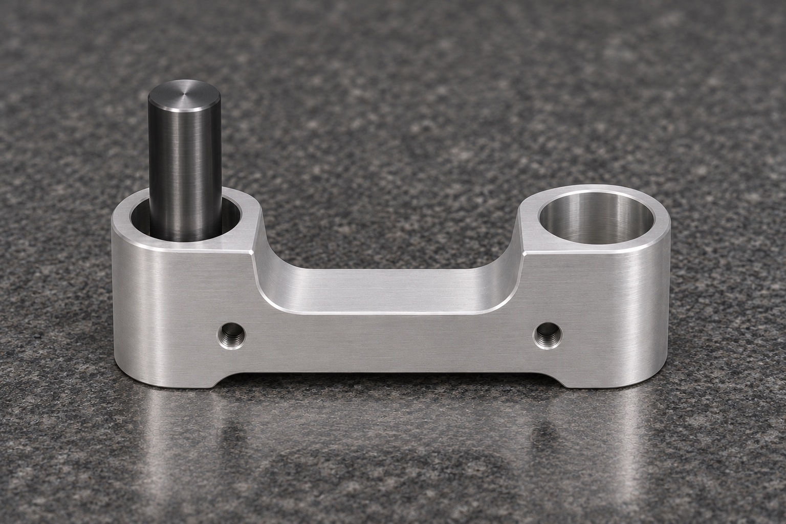
Mount two defined guide posts on a rigid test plate and verify their relation before introducing the carriage. Evaluate travel at several positions with the block free and, if specified, with the surrogate bracket installed. Track where any resistance appears and whether it follows the block or the test stand. Stop before forcing an interference. The purpose is to identify issues for design or manufacturing review, not to establish adjustment effort, a load capacity or a maintenance procedure for a real instrument.
Check if finish and assembly alter the result
After any agreed finish or bushing installation, repeat the characteristics affected by that step. A finish ridge at a bore entrance and a pinched bushing are different causes of interference. Record each condition and keep it linked to the part revision. Evaluate the hardware clearance separately from fit on the posts. Do not use the illustration as evidence that a coating, cleaner or lubricant is allowed. Selection and verification of those items belong to the responsible design and assembly teams.
Define visual checks at the actual interfaces
Inspect bore entries, outlet edges, the attachment face and the central relief for damage or residue. Distinguish a harmless cutter witness on a relieved wall from a raised burr that changes seating. Request an approved edge break where hardware or hands pass during assembly, while retaining the dimensioned contact area. Keep any wiping or cleaning material out of the bores after final inspection. An acceptable machined appearance does not establish cleanliness or disinfection performance in a clinical setting.
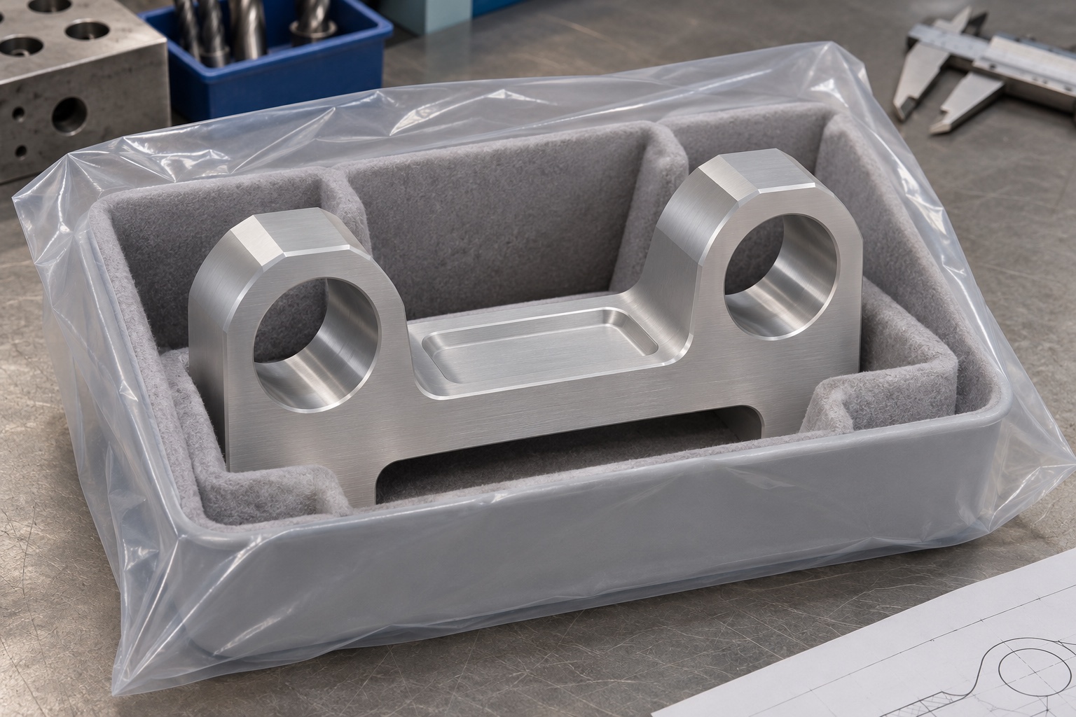
Support the bridge from nonfunctional surfaces
A fitted protective insert can carry the bridge under its exterior and leave the bore entries away from hard contact. Bag parts separately when needed to keep metal edges from rubbing. Put loose hardware in a separate compartment and keep identifiers off the front seating face. At receiving inspection, look for compressed inserts, impact marks or debris before repeating a fit check. This packaging is a handling example only; no sterile, validated cleanroom or storage-life claim is made.
Close the trial with an evidence checklist
A real trial would return the drawing revision, material lot, final surface condition, dimensional report and documented dry-fit setup. Call out any unresolved assembly movement, loads or stop checks separately. Do not turn a bench fit on two gauge posts into a compatibility statement for a commercial slit lamp. The device owner assesses the complete head support and clinical use. The machining example is useful because it makes the boundary between part conformance and device acceptance explicit from the start.
Manufacturer background reference: topconhealthcare.com.
FAQ
Was this carriage supplied to an ophthalmic equipment manufacturer?
No. It is a representative machining example with illustrative images. It does not report a customer, supply agreement, product approval, load rating or measured result.
What would the two vertical bores do?
They would interface with the defined guides in the concept. A released design would specify whether bushings, preload or controlled lateral float are part of that interface.
Why measure more than the bore entrances?
An entrance reading does not reveal axis direction, taper or the spacing deeper in the engagement. The inspection plan should represent the part of each bore that actually guides movement.
What does a dry-fit trial establish?
It can reveal assembly interference in the documented fixture and help decide what to investigate. It does not prove device reliability, patient support capability or suitability for clinical use.
Is the illustrated surface an approved finish?
No. The drawing and order would define whether the part is bare, coated or masked and which dimensions apply after finishing. The photo-like illustration is not finish evidence.
How should parts be identified at delivery?
Keep lot and revision identification legible on the packaging or an agreed nonfunctional area. Link the inspection report to that identity and avoid labels on guide surfaces or the bracket seat.

tanghangyun@oemach.com