
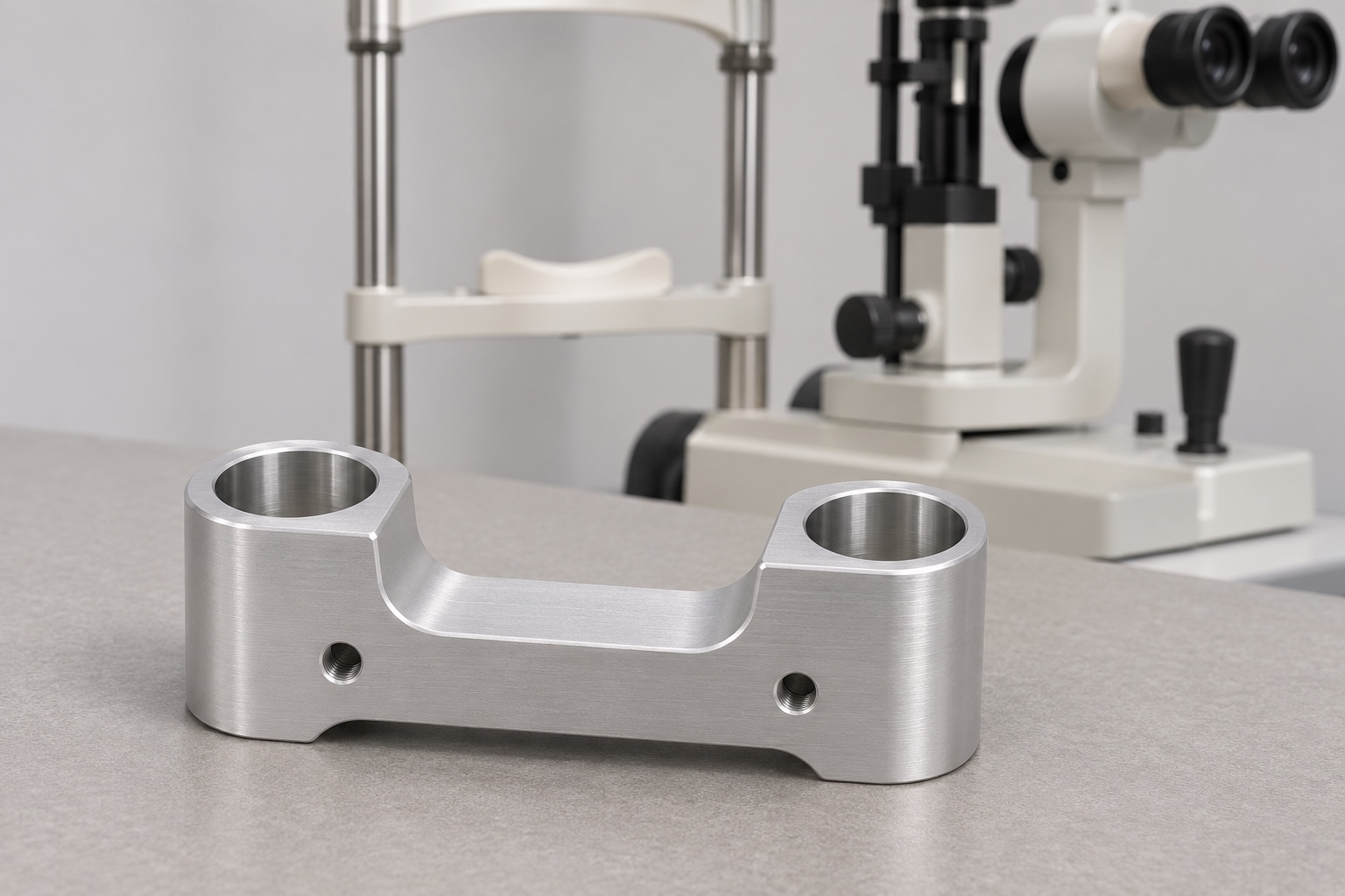
Separate the carriage from the patient interface
In a height-adjustable ophthalmic support, a carriage can connect a pad mounting bracket to vertical guides. Its task is to transmit motion and provide a stable attachment. The part drawing does not establish safe patient contact, permitted loads or the allowable adjustment range. Those are requirements for the assembled equipment and must be provided by its owner. The discussion here concerns a non-contact internal component and a bench method for understanding guide alignment before installing the complete support on a device.

Map what actually guides the motion
In a two-guide concept, the guides can be pins, rails or posts with replaceable bushings. Decide which surfaces control translation and whether one interface is intended to allow lateral float. If both bores are treated as rigid, an error in their spacing can cause binding even when each diameter measures within its own limits. Sketch the rail locations, carriage attachment and drive direction. This makes it easier to distinguish positioning, retention and travel limitation before dimensions are assigned to individual features.
Define bore spacing at the engagement depth
Center spacing taken near the entrance does not describe the relation between the axes through the entire engagement. A bore can be tilted or locally tapered while its entry measures acceptably. Identify the depth range that actually supports the guides. Specify the reference system with respect to the mounting face or other approved interface, and put clearance requirements on neighboring features. For a two-post example, inspection at more than one depth can help separate local form from spacing and angular error.
Evaluate the complete clearance stack
List the variation expected from both posts, their frame, the machined bores and any bushings or finish. An apparently generous clearance on the bare carriage can disappear once inserts or surface coatings are installed. Conversely, unnecessarily loose clearance may allow motion that cannot be corrected by tightening an attachment screw. Identify whether intended preload comes from a separate adjustment mechanism. A press fit for an insert is not equivalent to the running fit between the insert and the guide.
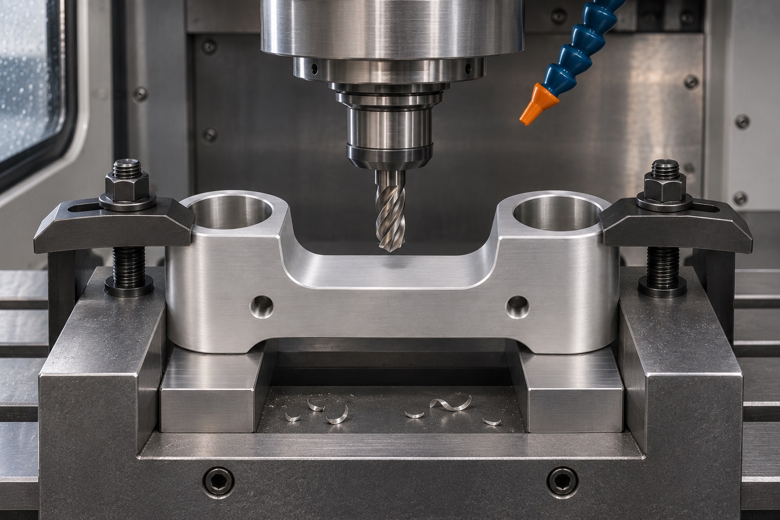
Plan how the two bores will be finished
Keeping the functional bores in one setup can reduce errors caused by transferring a datum. Finish cuts should reference the support condition and coordinate origin agreed for inspection. Tool reach, chip evacuation and the cross-section around each bore affect the operation. A narrow boss may flex under side clamping, then spring back after release. Review access to deburr exits and confirm that the blend does not remove usable engagement. Select tooling and parameters using the actual material and trial pieces.
Include finish thickness where it changes the fit
An engineering drawing should say whether fit surfaces are masked, finished after coating or inspected in their final coated condition. Do not leave that choice to inference from a general color note. A masked bore still needs a defined transition if a coating edge could create a lip. Where inserts are used, check that the installation process does not distort their internal diameter. Treat finish appearance, dimensional change and compatibility with maintenance products as separate acceptance topics.
Pair geometry with a functional gauge
A dimensional report can identify bore sizes, relative position and mounting face geometry. A two-post gauge can expose combined misalignment but does not tell which characteristic caused resistance. Use both when they answer different acceptance questions. The gauge needs a traceable definition of spacing, straightness and support. Be explicit about whether guide sleeves are installed and whether the carriage is fastened to a bracket during the check. A pass result is only meaningful under the conditions stated on the report.
When the first sample binds, compare the point at which resistance starts in several controlled conditions. A bore mouth may enter smoothly while a defect farther in blocks motion. A resistance change that follows the mating frame rather than the sample suggests checking the fixture before altering the CNC program. If only assembled samples bind, document the tightening order, contact face and side load. Keep the original sample and the baseline setup identifiable. That makes it possible to compare a proposed correction with the original condition without confusing a process change with a different trial.
Check motion without disguising a bind
Use an approved bench arrangement and evaluate motion along the intended travel rather than only at the start. A carriage can enter both posts easily and still tighten farther along if the guides are not parallel. Check whether tightening the mounting screws changes the response. Do not add lubricant, ream a hole or selectively swap pins without recording and approving the change. Record observations by setup so an issue in the test rig is not mistaken for a change in the part.
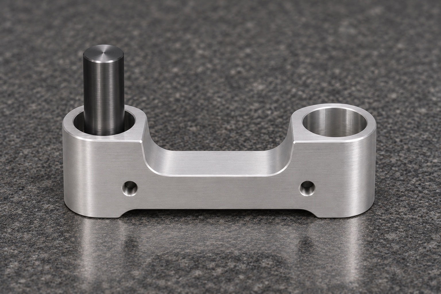
Keep assembly forces out of the free part report
In the free state, a relieved bridge may show different geometry than it does when tightened against a bracket. Define whether each tolerance applies free, mounted or both. If the drawing permits mounted inspection, identify the mating part, sequence and support. Inspect the mating frame separately when diagnosing alignment. A fixture that pulls the part into shape can hide distortion, while a bare part check alone cannot tell whether the complete drive introduces a side load. Keep those two conclusions distinct.
Design the edges for handling and service
The entry chamfer can help start an insert or post, but excessive chamfer can reduce effective engagement. At relief ends, avoid an edge break that intersects a reference face. Use a drawing note that identifies important edges rather than polishing everything indiscriminately. Verify that cleaning after machining removes loose chips from bores and blind details. Workholding witness marks, finish damage and burrs are different defects; define them by where they occur and how they affect the assembly.
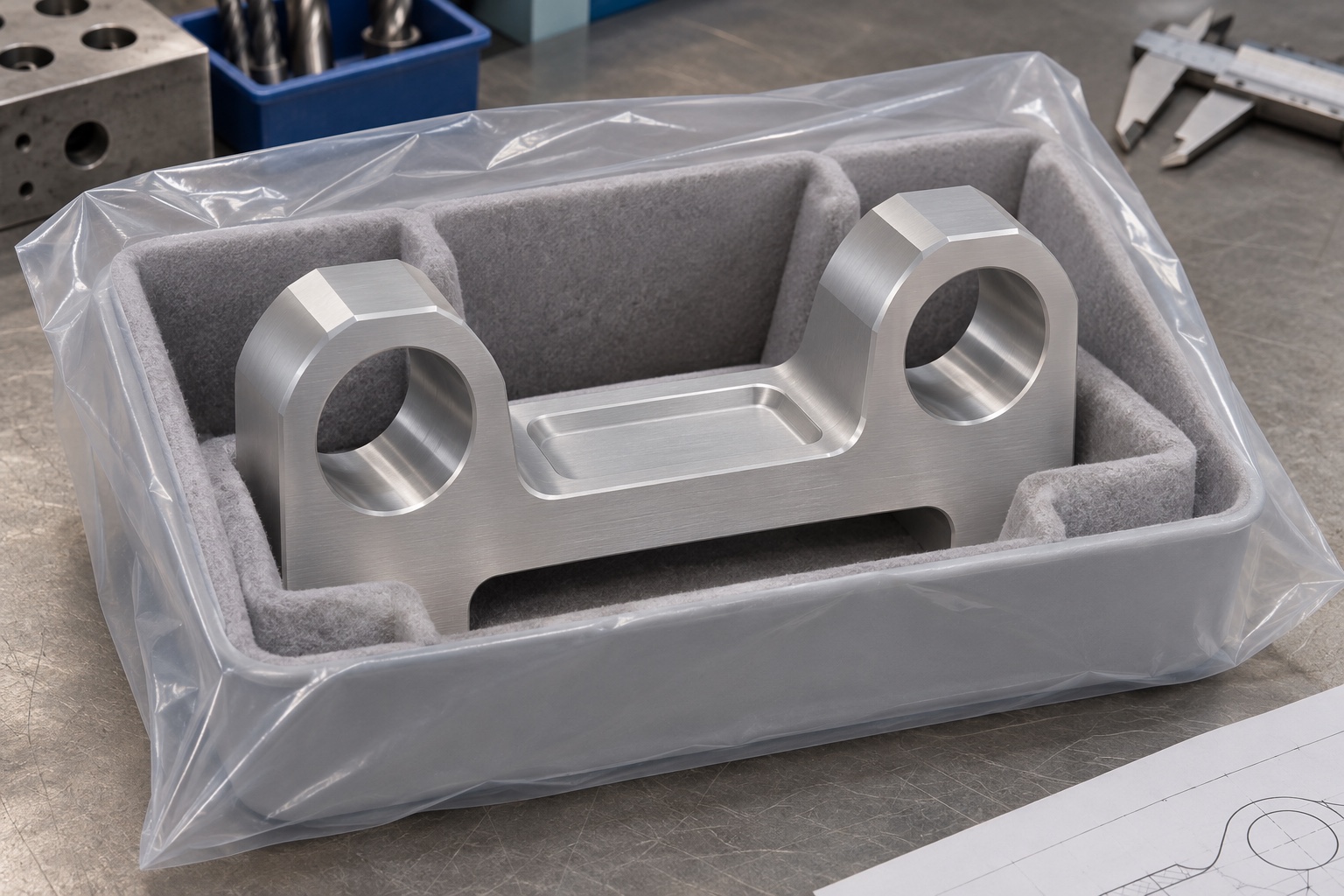
Keep protected surfaces protected in transit
The bores and seating faces should not rub against loose fasteners during shipment. A fitted insert can support a nonfunctional outer face and leave the bore mouths clear. If protective plugs are specified, check that they do not leave residue or deform an insert. Agree how the recipient identifies the revision and lot before opening the package. Protective packaging limits handling damage, but it does not imply a sterile barrier, a cleanroom classification or suitability for any clinical use.
Request evidence that can be compared at assembly
Send the drawing, mating post layout, target part condition and a description of the intended test arrangement with the request for quotation. Ask for measurement points and a method that the receiving team can reproduce. Separate machining acceptance from assembly validation, including travel limits and any checks that depend on patient contact or the complete instrument. When sample data are returned, link them to the revision and actual parts. A useful report should make a failure easier to isolate, not just record a pass.
Manufacturer background reference: topconhealthcare.com.
FAQ
Is checking both bore diameters enough?
No. The two sizes may conform while spacing, axis direction or local form causes a bind. Inspect the relationship that matters to the specified engagement and verify fit under the intended assembly condition.
Why use a two-post test fixture?
It can reproduce selected mating geometry and expose combined errors. It complements rather than replaces dimensional checks and must have its own documented alignment, condition and limitations.
Does the part drawing establish safe adjustment?
No. It describes one component. End stops, loads, motion, contact surfaces and adjustment behavior must be assessed on the approved complete equipment by its responsible owner.
Which state should be measured after coating?
Follow the controlled drawing. If guide surfaces are affected by the finish, measure the intended final state or document how masking or a finish operation preserves the required geometry.
What if the carriage binds only after tightening?
Check bracket flatness, screw sequence and test stand alignment before changing the bores. Compare free and installed measurements using the agreed mounting conditions and keep the results separate.
How should guide faces be shipped?
Keep gauge-critical surfaces apart from loose hardware and protect bore mouths from impact. The packaging and any inserts should be specified, and the part should be inspected again if the package shows damage.

tanghangyun@oemach.com