
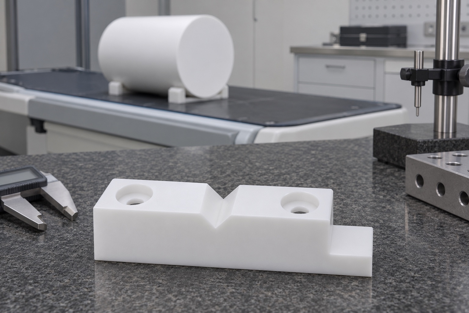
Define the example and its limits
This representative manufacturing example considers a small white acetal block that locates a cylindrical surrogate on a bench. The illustrative geometry has a shallow V notch between two counterbored mounting holes and an asymmetric end step. The notch and step make orientation visible in a concept image, but the approved assembly would define the actual stop surface. It is not a completed customer order, a device accessory approval or a claim about the quality of CT images. No measured fit or performance result is shown.

Plan the interfaces before creating tool paths
The underside of the block sits on a defined test plate. An external side reference establishes lateral orientation while the screws retain the block. The pair of screws is not assumed to locate the part within clearance holes. A controlled drawing would identify where the master cylinder touches and where it must clear other geometry. The operator should be able to see the end step during a setup trial. Leave any scanner table or installed stop interface unresolved until it is supplied by the owner.
Set the master and the reference conditions
Use a specified, identified cylinder for the bench seating exercise. The outer diameter, straightness and contact condition matter because they influence where the piece rests on the two flanks. A single reading taken with a different cylinder is not comparable. Establish the test plate reference before loading the master and record where the indicator touches. If the V is short, consider how the adjacent support carries the remaining length so the master does not tilt under its own weight.
Select and trace the blank
In the example, a white acetal blank is proposed for machinability and visual contrast against a test plate. The order would need an exact grade and stock form instead of a color description alone. Review flatness and stock allowance so the mounting plane and flange are not cut into damaged material. Capture the material lot when the blank is cut and carry that identification into the inspection and packaging records. Do not assume the pictured polymer or proposed screws may be used inside an imaging field.
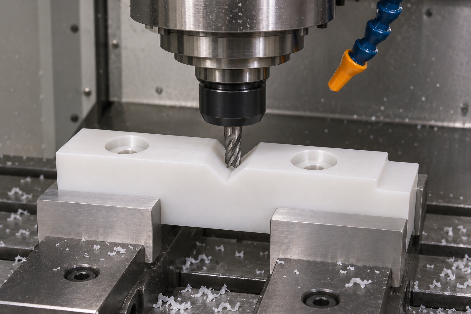
Establish the underside and rough the profile
A candidate first operation faces the underside, creates reliable side references and roughs the outside form. Leave enough stock for the finish cut on the V flanks and axial reference. Support the blank near the main loads, with fixture elements that avoid shifting the part during reinstallation. Clamping pressure and tool paths should be established on the actual material and machine. The machining illustration shows the general type of operation, not a fixture drawing, cutting parameter or validated process recipe.
Finish the V, counterbores and step
Finish the two V flanks so their relationship to the mounting plane is retained. Allow enough depth at the root to avoid seating on a corner radius. Drill and counterbore the retaining holes to the drawing and check that approved heads sit clear of the cylinder and fixture handling path. A separate finishing move can define the visible end step. Deburr hole exits and the outer profile, but do not blend the functional edges by eye after the dimensional check.
Inspect the unforced block
Place the part on its agreed supports. Check the base and the two flanks using a coordinate measurement or suitable bench method selected for access and uncertainty. Establish how the axial reference is located from the mounting plane and side reference. Record which surfaces were measured and the state of the part during inspection. Do not pull a rocking block flat with screws and then record it as conforming in a free state. A conditional installed inspection belongs on a separate line.
For the initial bench trial, compare installation in two stages. First reinstall the bare block and record its relation to the test plate. Then leave the block in place and reinstall the master. This helps separate movement at the bolted interface from variation introduced when placing the cylinder. If both stages contribute, do not add a tighter tolerance to the groove as a substitute for identifying the cause. Check the mounting interface, master contact and operator access independently. The example specifies no acceptance limits; they would be set by the equipment owner before any trial.
Reinstall the master to test the seating concept
A dry engineering trial would mount the block on the defined test plate and remove and reseat the master repeatedly. Record the readings by installation, rather than measuring the same seating several times and calling it repeatability. Observe contact on both sides and clearance from the counterbores. Check how the step guides orientation, including an intentionally incorrect approach when safe on the bench. None of these observations proves the holder will reproduce a complete scanner setup; that is a separate device-level check.
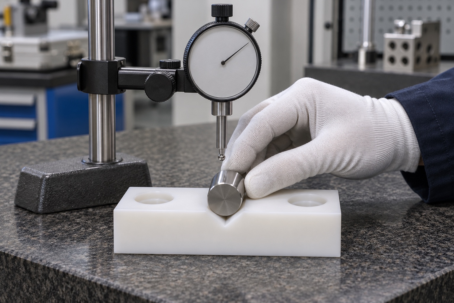
Agree what counts as a manufacturing issue
A chip on a flank, a raised counterbore edge or an underside dent can affect seating. Identify those as specific items in the inspection plan, not as a broad instruction to make the part look smooth. A tool witness line away from a seating face may be judged differently under an approved drawing. If a trial shows a shift, isolate the block, master and test plate before changing a dimension. Preserve the first set of findings so a corrected sample can be compared under the same setup.
Clean and identify without changing a contact
Keep the V and bottom face free of loose chips and verify that any approved cleaning leaves them intact. Avoid placing adhesive labels on the sides used as references. If the block is marked on a nonfunctional end, confirm the method and position do not create raised material or obscure the orientation step. The device owner separately defines compatibility with in-service cleaning and handling. No cleaning protocol, sterility classification or repeated-use validation is implied by the example or its illustrations.
Package by the outside shoulders
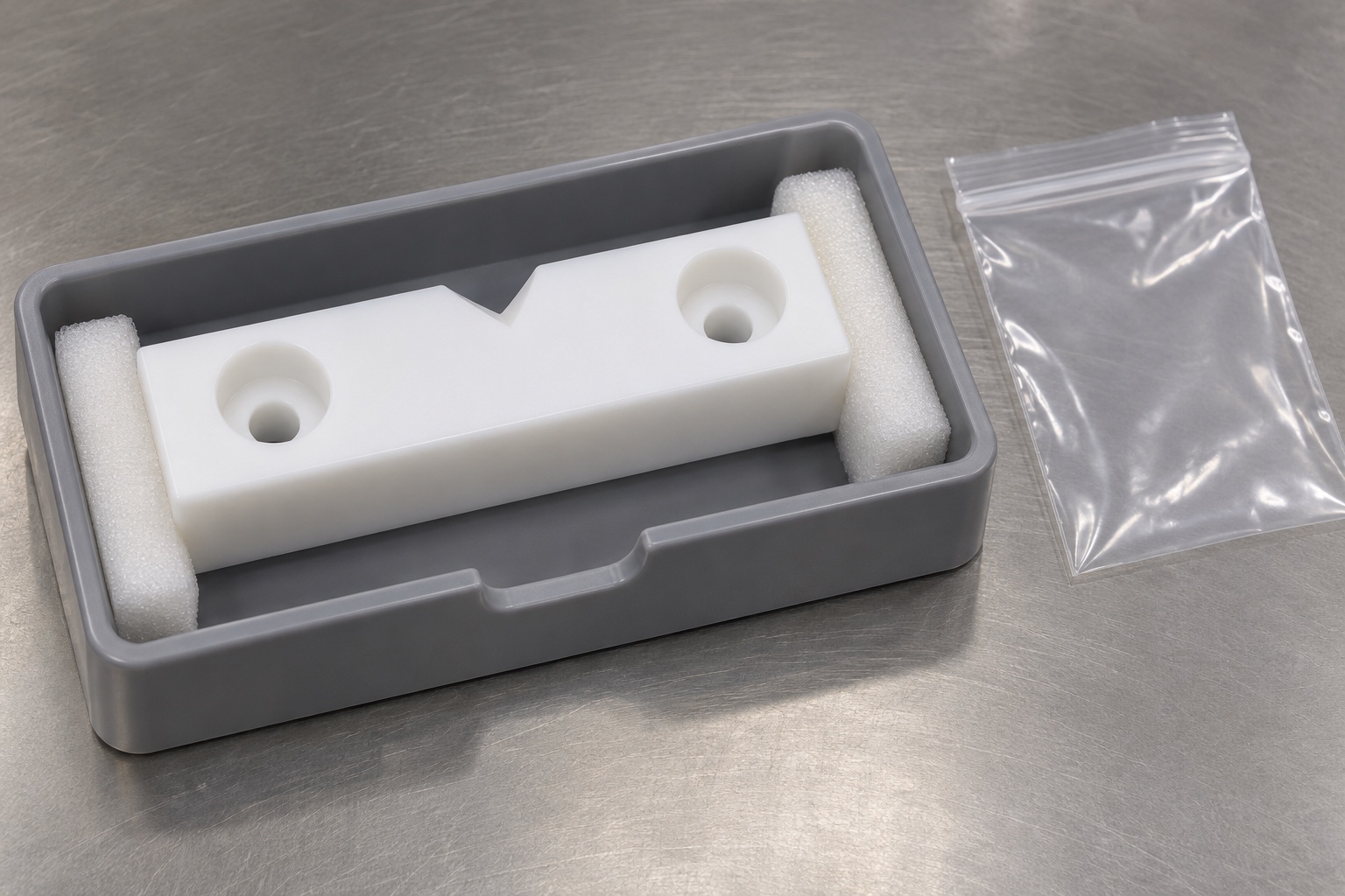
An insert can support the end shoulders and leave the V flanks open so they cannot rub against another part or loose screws. A protective overbag can separate the part from packaging debris where required by the order. Keep lot and revision identification readable outside the contact region. On receipt, check that the fixture has not shifted in the insert and inspect exposed locating surfaces before repeating a bench seating exercise. The illustrated packaging is protective only and is not a sterile barrier.
Transfer the evidence without extending its scope
For a real order, a release package would include a current drawing, material traceability, inspection report, definition of the master and bench setup, and agreed packaging. Report the condition of the master and any open installed interfaces separately. Leave scanner configuration, use approvals and image quality claims to the responsible equipment owner. That separation lets an engineer buy and evaluate the block without treating the supplier's part report as a scanner QA report. No production schedule or field result is asserted here.
Manufacturer background reference: www.flukebiomedical.com.
FAQ
Is this a real customer delivery?
No. It is a representative CNC manufacturing example with illustrations. It contains no customer identity, actual delivery, scanner approval or measured imaging result.
Why use two counterbores if the fixture needs precise location?
They provide retention for the concept. A separate, specified side reference may be needed to establish location because clearance under a screw head does not control sideways repeatability.
What features does the report distinguish?
It would separate the base reference, the two functional V faces, the end reference and the mounting holes. A bench seating trial with an identified master would be recorded separately.
Can the block be checked after tightening?
An installed check can be useful, but it does not replace free part inspection unless the drawing explicitly defines acceptance in that state. Report the fixture, support and installation conditions.
Is the example approved for an imaging field?
No. It concerns bench evaluation with a surrogate cylinder. An approved material and configuration review would be required for any actual imaging setup, including evaluation of fasteners and neighboring features.
What should be protected during shipment?
Keep the V faces, end reference and underside away from loose hardware and abrasive material. Use an insert that contacts suitable outside regions and keep identifiers off the functional surfaces.

tanghangyun@oemach.com